Continue to Site

Welcome to our site!

Electro Tech is an online community (with over 170,000 members) who enjoy talking about and building electronic circuits, projects and gadgets. To participate you need to register. Registration is free. Click here to register now.

  • Welcome to our site! Electro Tech is an online community (with over 170,000 members) who enjoy talking about and building electronic circuits, projects and gadgets. To participate you need to register. Registration is free. Click here to register now.

Create a start → stop/time on delay → reverse motion → stop circuit

Status
Not open for further replies.
Dougy83
Please describe 1, 2, 3, 4 in attached jpg. I apologize, trying to understand.

I looked into using a garage door opener with a micromatic delay on relay and the cost for the two is about $200. I received a bin of garage door motors for free and hoped to make the circuit board less expensive since I have access to the electronic components.
OK but the circuit Dougy83 is proposing is for a DC motor.
Your AC is going to need a start cap and special switching to work.
Start buy looking up some of the garage door opener wiring diagrams online to see how they are hooked up.
How many wires do your motors have coming out of them?
 
Here is what I found out today... the bin of garage door opener motors was in the garbage bin. ALL non working motors.
So I'm opting for a system with a 12VDC 24" Standard Duty Satellite Actuator motor ($60).

The better options are 32v actuators. I'd like to run these from one 12v marine battery.
How would the 32v system work off a 12 deep cycle battery? current draw is < 4amps. In the circuit is there any diodes, capacitors, etc needed?
 
Here is what I found out today... the bin of garage door opener motors was in the garbage bin. ALL non working motors.
So I'm opting for a system with a 12VDC 24" Standard Duty Satellite Actuator motor ($60).
Does it move fast enough?
How would the 32v system work off a 12 deep cycle battery? current draw is < 4amps. In the circuit is there any diodes, capacitors, etc needed?
It should run but will be much slower.
 
The better options are 32v actuators. I'd like to run these from one 12v marine battery.
How would the 32v system work off a 12 deep cycle battery? current draw is < 4amps. In the circuit is there any diodes, capacitors, etc needed?
It should run but will be much slower.
Yes it may run but it mite not start by its self.
It would be better if you had 2 or 3 batteries to run it off, 24 or 36 volts. I think that 12 volts may be to low but you can try it.
Just remember you need to try it under a load.
 
this can be done in different way too, if you are interested i can post you the schematic. as i understand you just have to press a button and wait, it will go, stop wait and return to the same position and stops. then you press again to start the next cycle.
 
this can be done in different way too, if you are interested i can post you the schematic. as i understand you just have to press a button and wait, it will go, stop wait and return to the same position and stops. then you press again to start the next cycle.
No wait at start.
 
I have attached another way to do it with relay and timer. for timer you can find it ready or still you can make one for you. i hope you will understand this diagram.
 

Attachments

  • garage door control.jpg
    garage door control.jpg
    67.2 KB · Views: 130
I apologize my delay in responding to this post. I have been out of town for work. I did not pick up the older garage door motors. I will however be looking inot another source tomorrow. I will be using 12v and 110v bidirectional motors.
I looked into using PLC for control but all the options found are a little more expensive than building a circuit board controller.

Dougy83, I really like your diagram and have some more ideas. LED lights for stages of program.
power on the board = red LED
amber LED = control side of relays has power
green LED = on when a circuit is active
a row of amber LEDs showing what stage board is in.

What additional components will I need besides LEDs?
 
You can add an LED across each relay to signal UP and DOWN states. The spare gate in the 4093 can connect to the output of the upper gate and the output of the middle gate to provide the WAITING indication (active low). The green LED will go on when any of these LEDs are on, which can be accomplished with three diodes forming a diode OR function of each state. The red LED connects across the power supply.

Each LED you add will need a series resistor, e.g. 1k for 10mA LED current. You'll need a buffer PNP transistor, such as a BC557, 2N3906, etc. to drive the WAITING LED and the three diodes, e.g. 1N4148, 1N4004, etc. for the green LED.

If you're using AC reversible motors, then you'll probably need to upgrade your relays to DPDT or add another SPST or SPDT.
 
Thank you again Dougy83. Would you be able to add these to the diagram? I do not have a clue where to put or what order to put the components you mention.
The motors I will be receiving, some are 12volts and others are 110volts.
 
Here's the schematic with the LEDs for the DC motor controller. Wiring for the AC motor depends on the type of AC motor you get.
 

Attachments

  • target actuator controller w leds.jpg
    target actuator controller w leds.jpg
    71.1 KB · Views: 129
what will happen if the PB is pressed in the middle of "down" travel? the response has to be inhibited.
If you press the button during the down travel, it will restart the cycle and revert to travelling up. If this is a problem, it can be inhibited by rewiring the switch ground connection instead through a diode to the output of the top inverter.
 
If you press the button during the down travel, it will restart the cycle and revert to travelling up. If this is a problem, it can be inhibited by rewiring the switch ground connection instead through a diode to the output of the top inverter.

quite possible to work so, and there may be another issue with your schematic during power up, due to capacitor it may trigger a start.
 
quite possible to work so, and there may be another issue with your schematic during power up, due to capacitor it may trigger a start.
Yes, good point. I guess the circuit needs a bit of reworking.
 
It looks like the OP has a PLC that he'll be using; if he has enough free I/O, then he can just use it for controlling the whole lot.
 
I did not get a chance to check out the used motor donor today. Hopefully weather cooperates tomorrow.

when the system is running, what happens if the start is activated? will it stall and reset? this would be a good addition.
I am wanting to build circuit boards for 10 targets.
Looking at a Smart Relay PLC to control random start times for each target board. (A PLC would be quite expensive for each target) so the circuit board is the less expensive option.
The reason I wanted to have LEDs on the circuit boards is for operation and diagnostics.
Red LED = board has power
Green LED = power thru action circuit
Amber LED = power to control circuit 2nd LED for complete action circuit
Blue LED = flashes for time delay (1 flash for 3s, 2 for 5s, 3 for 8s, 4 for 10s, 5 for 13s)
press button once → target pops up and stops → setting time on delay for reverse motion target down → target movement down and stops resets process for next press of start.
anything missing let me know... any other details needed...
 
At Broken Arrow Ministries we use the life skill sport of archery and share the gospel of Christ to at risk youth and families at festivals, concerts and family events we promote. We are a non profit with little to no finances. (Facebook/Broken Arrow Ministries Inc). My wife and I support most of the events and archery classes I teach, these monies contribute to cover the costs.
**we are not asking for money, and do not ask for money. we are only asking for assistance with ideas to make the events stand out to attract the teens and young adults.**
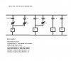
We have an archery venue with 15 stations, 100' wide and 45' deep. persently these 3D targets are stationary. Sometimes we use a rope and pulley but this has proven to be very labor intensive. We would like to have them move, similar to a garage door opener to open and close. These targets would move up and down. The use of a garage door system is about 250$ per unit and keeping track of all the remotes will add frustration. So I thought of using a popup system and and using a PLC to control trigget times for each target. Using a PLC for each target is more costly then the garage door systems. (even used).
If each target had it's on circuit board (all being the same with same settable delays function) the PLC could command a random sequence for each target to popup!

I can fabricate the stand, obtain used motors and new for about 45$, build a circuit board for about 30$. each target would be under 100$ with the exception of materials for the stand.

Here is the idea...
Build Objective 1:(ten)

1.Have a wireless command to start (future option)

2. Button is pushed and released, operates motor CW to move target (UP or forward)

3. Target moves to desired point and stops motor (circuit resets till button is pushed again)

4. Stopped target sets a time on delay to start motor again CCW (Down or reverse).
(Programmable delay start time for 0, 3, 5, 8, 10, 13 seconds)

5. Target moves to desired point and stops motor. (Circuit resets till button is pushed again)

Build Objective 2: (Two)

1. Have a wireless command to start (future option)

2. Button is pushed and released, operates motor #1 CW to move #1 target (UP or forward)

3. #1 target moves to desired point and stops motor #1(circuit resets till button is pushed again)

4. Stopped #1 target sets 1st time delay to start motor #2 CW (programmable time delay for 0, 1, 2, 3, 4, 5 seconds (UP or forward)).

5. #2 target moves to desired point and stops motor #2 (circuit resets till button is pushed again)

6. Stopped #2 target sets 2nd time on delay to start motor #2 again CCW (Down or reverse). (Programmable delay start time for 0- 15 seconds)

7. Stopped #2 target sets 3rd time on delay to start motor #1 again CCW (Down or reverse). (Programmable delay start time for 0-15 seconds)

8. Object moves to desired point and stops motor. (Circuit resets till button is pushed again)

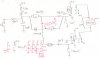
Where I work I have access to any kind electrical component that has been listed in the thread. I just do not know how to put it all together! With a diagram and known parts and their location I can put the system together.

I can use a PLC pretty well with robotics with these kids, the circuitry is where I lack knowledge.

There is the skinny on what we do and the idea we have.
why we do it.... the kids...
Engage-Inspire-Challange-Encourage-Empower
 
Status
Not open for further replies.

Latest threads

New Articles From Microcontroller Tips

Back
Top