Continue to Site

Welcome to our site!

Electro Tech is an online community (with over 170,000 members) who enjoy talking about and building electronic circuits, projects and gadgets. To participate you need to register. Registration is free. Click here to register now.

  • Welcome to our site! Electro Tech is an online community (with over 170,000 members) who enjoy talking about and building electronic circuits, projects and gadgets. To participate you need to register. Registration is free. Click here to register now.

computer Christmas lights

MrDEB

Well-Known Member
years ago I assembled a Compurterized Christmas light display but since sold the entire setup.
I recall the SSR or triac boards used an opti-isolator, couple resistors but instead of using a computer, I want to just use a PIC to drive the opti_isolator. Just started looking for leftover plans and parts but figure would ask first.
 
According to your last schematic, PORTB.1 is channel_10 output, which has a 10K pulldown.
Please show all the components currently attached to PORTB.1, including the toggle switch.
 
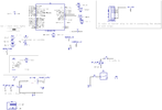
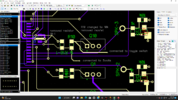
here is the schematic and screenshot of PCB revisions
 

Attachments

  • revisions.png
    revisions.png
    60.5 KB · Views: 149
  • Screenshot (19).png
    Screenshot (19).png
    195.3 KB · Views: 153
42 is the answer ti the Ultimate Question of Life, the Universe, and Everything, but posting the same schematic that nobody can make sense of 42 times still doesn't make it clear.

Would it be possible for you to draw an accurate schematic in the conventional and customary way with lines showing connections of the "LED matrix" showing the micro, the LEDs and their series resistors and whatever and everything that is connected to B1?

Can you turn on and off individually each of the LEDs?

You have at least one of the following (I suspect all three):

● Hardware problem

● A logic problem

● A software problem

Without an understable schematic showing the parts involved and testing to see if you can ACTUALLY control EACH and EVERY LED (show your code), this thread could go on 11 more pages and it still wouldn't work.
 
here is the schematic and screenshot of PCB revisions
So you've verified that there's nothing else connected to PORTB.1, correct?

What does the voltage on PORTB.1 measure when you have the toggle switch on and off?
Measure it at U1 pin 22.
 
here is the schematic and screenshot of PCB revisions
Your PCB shows 5V connected directly to pin 22...

The switch goes to pullup resistor R10. That's all. The other end of R10 (labelled +5V) goes through to pin 22.

Doesn't the PCB package verify the tracking to the schematic?? If not, you need a better package. EasyEDA definitely verifies connections.
 
Although I find MrDEBs schematics very difficult to follow, switch 1 seems to be correct. Pin is held high by R10 (assuming "5 volts in" is the 5V net) and pulled low by the switch. Or, (and it's very likely) did I miss something?

Mike.
 
I don't think he's verified that the LEDs turn on/off by whatever means he's using, and the logic in the code is really not discernable. The switch isn't controlling a single LED on/off (which is a good test of switch function) but instead does something else entirely.
 
Last edited:
My mistake! one big mistake!
AFTER I posted #202, did the dishes, cleaned the kitchen before my wife woke up then started watching tv and rethinking WHY my circuit doesn't work correctly.
I looked at the screenshot of the PCB I realized I have the 5volts and the ground connections backward.
Will correct it in the morning and hopefully, all will work correctly.
 
yes, the board is generated from the schematic.
In post #202 I made a slight change as I discovered I made a design error for the candle flames and wanted the pic to control when and how the candle flames are enabled instead of just turning on the ground to enable the candle flames.
In post#202 I removed the Q10 MOSFET since it was not needed and when with the revised schematic in post#202 BUT
when I made the revisions on the board I made the 5volts and ground (to the switch) backward thus prtB.1 will never go LOW. Later this morning I plan to remedy the issue.
If you look at post#202 you will see I have the net highlighted. After I highlighted and thought about the issue for several hours it dawned on me that I had the pullup resistor and switch to ground wrong.
I wanted the pic to control the candle flames instead of just the switch.
board corrections are coming.
QUESTION? in post#184 how with all the lines going everywhere is it easier to read? It was suggested to use labels instead of a mass of lines. And yes Diptrace highlights the connections.
 
Make sure your connections have net names (not just text labels) and are shown on the schematic.
Be consistent if you add labels... for example, in post 202 you have "5+VOLTS", "5+VOLT_OUTPUT", and "5 volts in" all used for (presumably) the same net.
 
YES
I check net connectivity while drawing a schematic.
I found AFTER a suggestion to wire the schematic "without wires" is easier to see what each connection is connected to the proper net. Doesn't help when having to make revisions to the PCB.
I made corrections and the desired led is enabled but need to disable the LED AFTER the route to the ground is broken. In the final project, the toggle switch switches the LED OFF / ON
 
FINALLY got to power up the board and had to switch a few wires around as they were not the correct "letter"
After having ALL 9 Mosfets on I noticed 7805 getting hot. Kinda expected this but hopefully toggling the Mosfets OFF then ON may be a short delay to cycling the Mosfets ON/OFF (multiplexing?)
Have one Mosfet that appears not to be enabling the red strips.
Will track the issue down. What with 32 wires it doesn't surprise me.
What a mess with all them wires.
 
I believe you're powering a mess of LEDs from 5 volts, and switching them to ground using N-channel mosfets. You're needlessly torturing the poor 5 volt regulator. It would be better to power the LEDs from the 12 volt supply (with appropriate resistors) since you're already using mosfets to switch them. There's no reason to burden the 5 volt regulator with their load.

Remember, power dissipated by a linear regulator is the voltage drop × the current. More than half the power used is going into heating the regulator.

Pd = (Vsupply – Vreg) x current in amps
 
After having ALL 9 Mosfets on I noticed 7805 getting hot.

If you're talking about the channel1-channel9 outputs I thought those strips were using 12V as the power.
If so, as long as all the other led outputs are turned off (the row-column matrix, headlamp, etc) then there should be minimal load on the 5V regulator and it shouldn't be hot. Turning on the channel1-channel9 strips shouldn't change that very much at all (unless you've wired things differently).

Since you have 12V going into the 7805 it doesn't take much current for the power dissipation to go up (and get hot). For example, with 100mA out you'd have Power = (12V-5V) x 100mA = 700mW (or 0.7 W). That may not sound like much, but with a TO220 case that's enough to make the temp rise about 60degF
 
Tumbleweed hit it on the head. I looked at my calculations and I come up with 5ma per channel = 45ma (1K gate resistors)
the 4 LEDs with 320 ohm resistors = 64ma
total current draw = 109ma
Either way, I fried the 18f2221
going to increase the 4 resistors connected to the 4 LEDs to start with..
I have yet to connect the LEDs in the row-column matrix and toggle the Mosfets to make the 12v strips appear ON
I looked up paralleling the 7805 but that's not possible.
Hopefully, find out WHY my red strips don't come on.
 
Tumbleweed hit it on the head. I looked at my calculations and I come up with 5ma per channel = 45ma (1K gate resistors)

Normally, the gate of the mosfets won't be pulling anywhere near 5mA. They will be uA (except while the fet is switching).

Either way, I fried the 18f2221
going to increase the 4 resistors connected to the 4 LEDs to start with..
I have yet to connect the LEDs in the row-column matrix and toggle the Mosfets to make the 12v strips appear ON
Which 4 LEDs are you talking about? I don't see the 18f2221 frying, but I don't know what you're connecting to what.
 
MrDEB, nobody is sure exactly what you have connected to what. For the LEDs you're trying to make work at this exact moment, could you start with a blank sheet and show one complete set:

LED

Series resistor

Mosfet

Power connection (+5 or +12)

Ground connections

Resistors connected to mosfet and where they goes

Connection to the port pin, including any series resistor

Nobody really is certain of what you've got connected where. Please start fresh and show the complete and actual circuit for one LED. Please don't copy and paste the "schematic" you've posted so many times because nobody can understand it. Just the entire circuit for one LED.
 

Latest threads

New Articles From Microcontroller Tips

Back
Top