Continue to Site

Welcome to our site!

Electro Tech is an online community (with over 170,000 members) who enjoy talking about and building electronic circuits, projects and gadgets. To participate you need to register. Registration is free. Click here to register now.

  • Welcome to our site! Electro Tech is an online community (with over 170,000 members) who enjoy talking about and building electronic circuits, projects and gadgets. To participate you need to register. Registration is free. Click here to register now.
Status
Not open for further replies.
Hello everyone. I am doing a project in which I use a buck converter to convert high vtg to low vtg.
Actually the input to the buck converter is from a solar panel which puts out 560 mA constant current and 34 V.
And output is a 12V lead acid battery. The N- Channel mosfet is used at high side and is driven by an isolated driver (I used separate 12V battery to drive the MOSFET). I used PIC controller to give pulses at 20 KHz. I also used pot to vary duty cycle. I calculated inductor value from some website (there was an onlime calculator) By calculations it was 40 mH. I my have made inductor using a ferrite core transformer (taken out from 24 W old power supply ) Diode used is a fast recovery diode.
So my problem is when everything is connected properly the output of buck doesn't give out enough power. The output is pulled down to battery vtg (as expected) And current going into the battery approx. 400-500 mA. And inspite of changing duty cycle power stays (say 500mA × 12 V) 6 W.
And at input side current from panel is 500-600 mA and panel vtg varies with varying PWM ( with pot ) from 12 V ( exceptionally battery vtg) to 34 V. Now power at input as observed is (34 V × 500 mA) 17 W and ouput still remains 6 W ( at battery side).
Plz help. I have read most of the designs available online. Also increased the inductor value to about 90 mH. But nothing worked.
 
You would be more likely to get help if you posted the schematic of the converter.

Les.
 
This is the diagram of the converter.
 

Attachments

  • 20160626_142848.jpg
    20160626_142848.jpg
    1.2 MB · Views: 449
Hy Pravin,

Is your location perhaps Nashik rather than Nasik which is in Iran?

Can you provide a full schematic and show component types? That will help us sort your problem.

spec
 
Last edited:
I don't have the full schematic for now. The components other than these are just PIC microcontroller and a pot.
MOSFET is P55
Inductor is homemade 40 mH
And diode is a fast recovery diode removed from a SMPS and is ok.
 
I don't have the full schematic for now. The components other than these are just PIC microcontroller and a pot.
MOSFET is P55
Inductor is homemade 40 mH
And diode is a fast recovery diode removed from a SMPS and is ok.
Thanks

What is the driver type?

spec
 
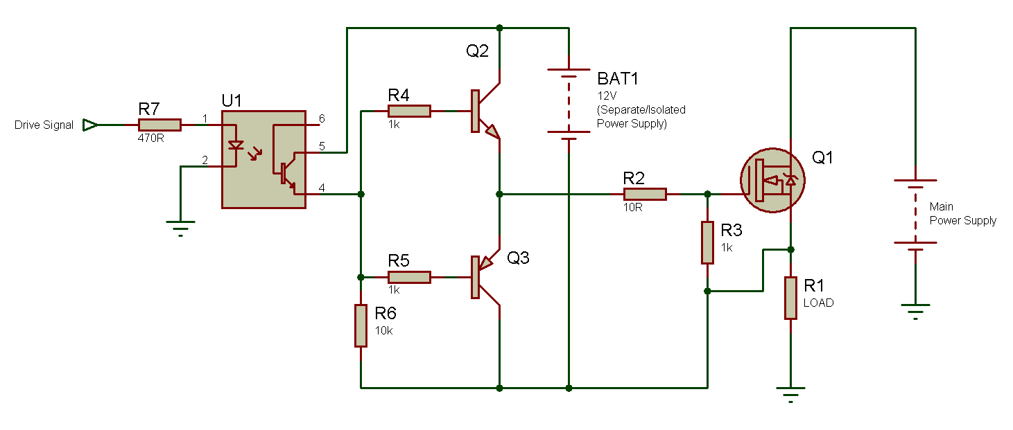
This driver:

What U1 have you used?
What type of transistors are Q2 and Q3?

(1) One of the first things I notice is that Q1 gate stopper R2 (10R) is shown in the wrong place. R2 should connect physically directly to the gate of the NMOSFET to stop Q1 from oscillating. So R3 top should connect to the left of R2.

(3) The other thing is that your layout may be causing the NMOSFET to oscillate. Can you post a picture of your layout.

(4) There is no decoupling capacitors shown. You need a 22uF ceramic capacitor connected physically from Q2 collector to Q3 collector.

(5) Another 22uF ceramic capacitor is required physically between the drain of the NMOSFET Q1 and OV (shown as ground on the driver schematic).

(6) Note if you do not have any 22uF ceramic capacitors, a 100nF ceramic capacitor in parallel with a 22uF aluminum electrolytic capacitor will do.

(7) The driver looks very slow, due to the high value of R6 (10K). This could also be causing problems.

(8) In general, I hate to say this, but that is not the best driver circuit I have seen.

(9) You might also like to try putting a 2m2 F (2200 uf) capacitor or larger across the output of the solar panel close to the NMOSFET unless the solar panel already has a large capacitor across it.

spec

isolated+ps.png
 
Last edited:
Yes. I have used separate battery for its supply. There is no problem in driver stage because I get 20 KHz at the gate of the MOSFET wrt to it's source ( measured using multimeter as I currently don't have access to scope. )

U1 is EL817
Q2 BC547
Q3 BC557
 
Last edited:
Check your solar panel ratings. I'm not aware of any panel which can alone provide a constant current, despite variations of load and insolation. Is 560mA perhaps the maximum current rating, and 34V the maximum voltage?
 
It is I(mpp) and V (mpp). Yes it provides 560 mA ( in my case constant means it does not vary when I change duty cycle but voltage changes only ).
 
Check your solar panel ratings. I'm not aware of any panel which can alone provide a constant current, despite variations of load and insolation. Is 560mA perhaps the maximum current rating, and 34V the maximum voltage?

Pravin,

In view of Alec's post above, can you ensure that the solar panel is in bright sunlight and connect a 56 Ohm 20W, or greater, resistor across the solar panel output terminals and measure the DC output voltage from the solar panel.

spec
 
I can't find 56 Ohm 20W resistor.
These specs are given at the back of the panel.

The absolute value of the resistor is not critical. I just want to establish in practice what the output impedance of the solar panel is. You can make up an equivalent resistor by connecting resistors in series and parallel to make up the resistor value required and the wattage. Alternatively you could use three 6W filament automobile bulbs connected in series.

Yes, I'm sure you would have checked the specification of the solar panel before starting the project, but it is always best to test a actual component in the event of problems.

spec
 
Last edited:
Status
Not open for further replies.

Latest threads

New Articles From Microcontroller Tips

Back
Top