Continue to Site

Welcome to our site!

Electro Tech is an online community (with over 170,000 members) who enjoy talking about and building electronic circuits, projects and gadgets. To participate you need to register. Registration is free. Click here to register now.

  • Welcome to our site! Electro Tech is an online community (with over 170,000 members) who enjoy talking about and building electronic circuits, projects and gadgets. To participate you need to register. Registration is free. Click here to register now.
Status
Not open for further replies.
For 40 mH I think I have 4- 500 turns. So now I need only 40- 50 turns. Right?

And the inductor is a transformer EE type which I found in an old smps.

Thanks.

That is correct: inductance is proportional to the square of the number of turns.

The energy in an inductor is proportional to the square of the current flowing through it.

Just to check, the EE core is ferrite not steel laminations.

spec
 
look for a handy RLC vs Z loglog graph on the web and understand what I said about L/R ratios and impedance at switching freqiency and impedance ratios for power transfer.

Regarding the PV capacitance. All reverse biased diodes have capacitancemand current sources are high impedance at DC.
For buck regulation the L/C ratio and self resonant frequency SRF, of L and any souce and load C , SRF MUST be greater than the at least 10x the PWM rate. So the bulk capacitance of the panels may have a low SRF but this is improved by smaller Plastic C values in shunt.

Determine or measure the SRF , correct impedance (f) and ESR of all critical energy storage components and active switches, incl diodes.

Remember for L in continuous mode or discontinuous mode you are only storing energy for 1/2 cycle. P=1/2 LI^2= 1/2 CV^2. where we are only computing the changes in I or V before and after each partial cycle . This is the energy you want to transfer with no losses from Current Source to CV near zero Ohm battery. delta P=Delta VI

If you try,,you will learn much faster by understanding these basic principles.
 
BTW your inductor outght to be on the order of 10-50 uH not mH, heavy magnet wire air core so no saturation remenance issues like a small woofer crossover coil for a 50-200W Watt capacity.

C_bat might be >ten thousand Farads but lead inductance requires a plastic cap at source to suppress EMI and prevent spikes, same with PV being a few dozen uF, it needs a cap to lower impedance up to 10x the PWM rate, then the switch is the lowest ESR or RdsOn and the LC ESR's will contribute to loss, and may require Cap ripple current spec checks for RMS on edges, not DC to Pk-PK ripple current for full duration of cycle. Can U do math?

capiche?
 
Last edited:
560 mA constant current and 34 V.
And output is a 12V lead acid battery.

Have you ever heard of MPTT max power transfer tracker? Basically this is not critical if you have a PV VLoad/Voc ratio 75-80% , otherwise efficiency drops quickly away from this. Yours is 14V/ 34V , I believe, or 41% so this is half your ideal efficiency of 22% from , so you can expect half the solar efficacy or output DC power , I am guessing 19W panel?

Can you match your PV array to 17V by converting part series to parallel? Otherwise you need a dual converter. CC to CV (MPTT) then DC-DC to charge battery
 
Last edited:
I can't find 56 Ohm 20W resistor.
These specs are given at the back of the panel.
use a 300W halogen lamp or similar and measure R cold. You will only be expecting to see 20W max...and again targeting PV ideal, = V_load/V_no load=80% or 75% at low solar input.
 
Have you ever heard of MPTT max power transfer tracker? Basically this is not critical if you have a PV VLoad/Voc ratio 75-80% , otherwise efficiency drops quickly away from this. Yours is 14V/ 34V , I believe, or 41% so this is half your ideal efficiency of 22% from , so you can expect half the solar efficacy or output DC power , I am guessing 19W panel?

I am using this converter for mppt only. That's the aim of this project.

I have connected two 10W panels in series whose Vmpp is 17 V each. So in series it becomes 34 V.

So do you suggest to parallel the panels to get 17 V as Vmpp?
What will be the effects?
 
I am using this converter for mppt only. That's the aim of this project.

I have connected two 10W panels in series whose Vmpp is 17 V each. So in series it becomes 34 V.

So do you suggest to parallel the panels to get 17 V as Vmpp?
What will be the effects?

You have n ot specified in your design that you had MPPT or Voc ( open cct)

Obviously if you plan on PMMT, either series or parallel works. I thought you meant 34V open circuit.

Redesign as I indicated by carefully choosing each part for impedance , SRF and ESR
. 17/21.5= 79% = 34/43V is OK This drops to 75% at low solar input.
upload_2016-6-26_23-57-11.png
 
Posts#42, 43, 44, 45, 47 above.

Hy Tony,

The OP has wisely chosen a low switching frequency which minimizes any problems with self resonance etc that seem to trouble you so much.

In terms of maximum power point tracking (MPPT), that can be done by the MCU, if necessary, by monitoring the solar panel output voltage and current and adjusting the pulse width modulation mark-to-space ratio accordingly. The OP has stated that he is presently doing this manually by adjusting a potentiometer.

The graph you show for maximum power transfer and your statements have confused the OP as evidenced by his question about placing the solar panels in parallel rather than series. There are two aspects:
(1) Power transfer from the solar panel
(2) Efficiency of the switch mode power supply.
and you have not clearly differentiated between the two.

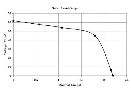
I find that type of graph confusing anyway, although it is used quite often. The characteristic of a solar cell is essentially a constant voltage (band gap) with a varying current capability proportional to the intensity of the incident light. It is not, in principle, a constant current with varying voltage. As such it is very similar to many load lines.

solar2.jpg

DI30Fig01.gif
Because of this, in principle, MPPT is not exactly rocket science, although to read some of the information on the net you would think otherwise. No doubt MPPT gets more complex with some solar panels, and if you are trying to extract the last 5% of power.

But the OP has not asked about maximum power point tracking. He is merely asking why his inverter is inefficient (not working).

To a first order approximation a buck switch mode power supply does not care what the input voltage is, as long as it is a few volts above the output, as it operates on constant power not constant current like a linear regulator.

I had already explained about the inductor value and showed the calculations.

I know you are a learned fellow, with a great deal of experience, but in general it is important to make sure that theory, advice, and warnings are targeted at the project in hand, both in principal and degree and to answer the OP's questions in terms commensurate with his level of expertise.:)

spec

PS: Here is an ON Semiconductor application report which includes an overview of solar panels: http://www.onsemi.com/pub_link/Collateral/DN06054.PDF
 
Last edited:
What is the minimum current you want through the inductance?
 
1) The OP has wisely chosen a low switching frequency which minimizes any problems with self resonance etc that seem to trouble you so much.

2) In terms of maximum power tracking, that can be done by the MCU, if necessary, by monitoring the solar panel output voltage and current and adjusting the pulse width modulation mark-to-space ratio accordingly. The OP has stated that he is presently doing this manually by adjusting a potentiometer.

3) The graph you show for maximum power transfer and your statements have confused the OP as evidenced by his question about placing the solar panels in parallel. To a first order approximation a buck switch mode power supply does not care what the input voltage is, as long as it is a few volts above the output, as it operates on constant power not constant current like a linear regulator.

3) But the OP has not asked about maximum power tracking. He is merely asking why his inverter is inefficient (not working).

4) I had already explained about the inductor value and showed the calculations.

I know you are a learned fellow, with a great deal of experience, but in general it is important to make sure that theory, advice, and warnings apply to the project in hand, both in principal and degree.:)

spec

PS: Here is an ON Semiconductor application report which includes an overview of solar panels: https://www.onsemi.com/pub_link/Collateral/DN06054.PDF

The OP would do himself a favour to report a complete block diagram of his design with average DC and AC ripple currents and voltages at each stage using his best with best tools and shortest leads or use twisted pair or coax. to a good meter to avoid antenna effects of x MHz transients.

1) All inductors are self resonant, above which they behave more like capacitors from inter-winding capacitance of 500 turns at 20kHz. This is NOT what you want between your switch and DC-DC difference and thus less current is stored in the core and the PV voltage power is transfered.

Best case energy of 20Watts is with the PV loaded at 80% Voc MPT for a PV which it is the best matched load voltage to deliver the most current*voltage product. current source only at this voltage.

PV's are not true current sources but current sources with voltage limits "almost like a zener", so MPT is the 80% maximum power just below this "zener -like" open circuit voltage. It does not shunt current internally, rather it affcts the efficacy of converting light energy to electrical energy. EVen at 80%Voc, efficiency is only ~ 20% give or take. It is not an LDO just an impedance matching of a lousy current source by voltage ratio.

You dont use a potentiometer to create this 17V!

You load the PV (current source) with either a fixed battery of 17V ( and a full charge switch) or a fixed DC-DC converter of 17V from the panel. Then use another DC Converter or battery to store at 12V . That's for max efficiency. So a MPPT regulator is the 1st DC-DC regulator, but it hunts for max power depending on temp and available input solar power.


THe reason why is MPT is because Voc drops 10% with rising temperatures( actually a linear NTC) and another 10% lower solar input power , yet Pb acid batteries rise 8% in voltage from 0 to 100% SoC. So this almost 30% swing means to lose efficiency unless you use a 98% efficient MPPT regulator then a 98% efficient Buck regulator.

Try to,understand this then your design flaws will become clear.

spec is correct, in that you CAN make a better Buck regulator with your (too big) inductor at say 200Hz , but then you need a big Storage cap on the PV array. So the standard soluton is eliminate both and use a 50uH choke at 20kHz or whatever works at desired range of duty cycles and does not exceed 0.6 Tesla for a ferrite core( common limit)
 
Doh. man you simply use your PWM with a plastic cap and the duty cycle of the <50 mΩ switch ESR is multiplied by the off/on duty cycle and now you have a variable active load with narrow pulse currents integrated by the cap.

. Add some AWG 18 wire on a nylon screw in a coil to make 20uH and now you have lower ripple voltage Buck regulator to adjust the PV voltage near1 17 V and measure the Idc vs Vdc , then verify Vac ripple. Then you can plot your own P vs V vs I curve like the one I showed.

For bonus points characterize the P vs voltage on a photodiode and a diode for Vf vs T from a low power LDO to adjust V using an Op Amp with the correct offset from 16.5 to 17.5 vs temp and brightness

OR use a MPPT regulator to hunt for the max power point.

But then to get all of the power into the battery , you have to keep the PV at 16.5-17.5V or MTP with a second DC-DC converter and regulate the current charge to the battery, then regulate the maximum float voltage to 14.2 for flooded cell battery with a power schottkey diode to prevent night time PV leakage from draining the battery.

These are ballpark values, your results may vary slightly.

Got it yet?
 
Last edited:
Ok, using this calc I see the current through the 40mH inductance hardly changes, no problem if you have room for the inductor.
http://schmidt-walter-schaltnetzteile.de/smps_e/abw_smps_e.html

I suspect the issue is the inductor, it often is on a new design smps.

Have you measured its inductance.
If any mistakes or oversights have been made during inductor design this would cause something like this to happen.
40mH is a very high value, that would need a lot of wire, what is the dc resistance of the inductor, maybe its so high that its preventing it from charging.
Something else that occurred to me, what fet are you using, if your driving it from the pic then you'll need a logic level fet, a standard one will not turn on fully with 5v drive from the pic and might cause this issue.
Have you probed around the circuit using a 'scope to see whats going on?
 
Status
Not open for further replies.

Latest threads

Back
Top