Continue to Site

Welcome to our site!

Electro Tech is an online community (with over 170,000 members) who enjoy talking about and building electronic circuits, projects and gadgets. To participate you need to register. Registration is free. Click here to register now.

  • Welcome to our site! Electro Tech is an online community (with over 170,000 members) who enjoy talking about and building electronic circuits, projects and gadgets. To participate you need to register. Registration is free. Click here to register now.

Basic problem with transistors

Status
Not open for further replies.
1) The protection diodes for the BJTs were eventually deemed unnecessary, correct?
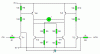
That depends on the transistors: if the Vce is rated for more than 45V you'll probably be all right.

2) Given that the stall current of the motors was measured at about 750mA, with a peak of 1.05A, will the circuits be able to handle this, or require the current to be limited to avoid destruction when the motors stall? I'm fairly certain the motor will survive okay, just need to double-check that the BJTs, diodes, and especially my microprocessor won't be adversely affected.
Same answer as question 1: it depends on the transistors. Again if you choose transistors with a high enough Ic rating then they'll be able to withstand the stall current.

How many stalled motors are you going to have operating at the same time?

Use thick enough gauge wires to the batteries and wide enough PCB traces to adequately carry the required current.

Did you check out the price of the high gain transistors I posted?
**broken link removed**

I don't think they're expensive but it depends on the cost of your product. If this was a one off for me then a 38p rather than an 5p transistor wouldn't put me off but if I wanted to outsource production to China (obviously I could buy both transistors in 1000s for 1/10th of the price from Rapid) and sell them for £1 per piece then it certainly would.

Regarding the tolerances and typical debate:

It depends on what you're making, in this case a low saturation voltage is desirable but not really critical. Also the chances that a high side transistor and a low transistor both have the worst case saturation voltage is pretty low.

Given this, I think it's al right to use typical figures in this case. If you're worried then it might be sensible to consider the worst case for the high side and typical for the low but assuming worst case for both is just paranoid. If it could blow up or just completely fail to work then I'd agree but it won't, the worst case (pretty unlikely) is that it won't perform as well as to be expected.
 
Last edited:
Just so that this doesn't get lost in the midst of the 'typical transistor' discussion :rolleyes:

A couple of quick points to confirm with whoever might be able to answer these:

1) The protection diodes for the BJTs were eventually deemed unnecessary, correct?

2) Given that the stall current of the motors was measured at about 750mA, with a peak of 1.05A, will the circuits be able to handle this, or require the current to be limited to avoid destruction when the motors stall? I'm fairly certain the motor will survive okay, just need to double-check that the BJTs, diodes, and especially my microprocessor won't be adversely affected.
 
I've just answered your questions, was there anything you didn't understand?
 
How many stalled motors are you going to have operating at the same time?

There are five motors, but it seems extremely unlikely that two separate motors will be stalled at once. They will only occasionally even be operated at the same time.

Hero999 said:
Use thick enough gauge wires to the batteries and wide enough PCB traces to adequately carry the required current.

Will do! I don't remember the rating of the wire I'm using but I'm pretty certain it can handle anything this circuit will output; as for the PCB, as I mentioned previously I don't yet have the equipment to design / etch my own PCBs so I'm using tripad board... actually I may get some stripboard as I quickly discovered when planning a different project on this board that strips of 3 is not enough for most circuits, it'd involve a rather stupid number of adjoining cables.

Hero999 said:
I don't think they're expensive but it depends on the cost of your product. If this was a one off for me then a 38p rather than an 5p transistor wouldn't put me off
5p transistors... I have GOT to find a better supplier than maplin. The cheapest transistors they sell are 21p each; works out to 12.5p per unit when buying 20+ of them. I'll take a look at rapid and see how their prices compare to maplin's... come to think of it, I think that's where I got my reel of lovely violet wire :D I specifically ordered it online from them despite high delivery cost because cut cable at maplin was ludicrously priced.
 
Before we were arguing that the transistors do not have enough base current for a 200mA motor. Now the motor draws more than 1A and nobody says anything?

If your transistors are weak (but passable) then the motor might not even start running.
 
So to be clear, with the high-gain BJTs, or 6 "standard" BJTs instead of the four, as shown in Hero's earlier schematic, there shouldn't be a problem with passing a current approaching 1A in the stalled condition, even with the microprocessor current through the bases being limited to 4mA?
 
Last edited:
**broken link removed**

Just to check, are the whole range of transistors on those two links high-gain transistors? One product on the second link seemed to be specifically marked 'high gain', and none of the others on either of the pages specified that.
 
Before we were arguing that the transistors do not have enough base current for a 200mA motor. Now the motor draws more than 1A and nobody says anything?

If your transistors are weak (but passable) then the motor might not even start running.
You obviously haven't read the datasheet for the ZTX690B.

Maximum Vce = 0.5V@Ic = 1A & Ib = 5mA.
Typical Vce about 0.35V@Ic = 1A & Ib = 5mA
Typical Vce = 0.1V@Ic = 200mA & Ib = 2mA.

**broken link removed**

Just to check, are the whole range of transistors on those two links high-gain transistors? One product on the second link seemed to be specifically marked 'high gain', and none of the others on either of the pages specified that.
The ZTX690B is the NPN version of the ZTX790A. It's fairly similar except it's NPN and that the voltage rating is slighlty lower (probably because it's B rather than an A) and it has a higher gain (NPN transistors normally do).

The datsheets list the gains and saturation voltage under cetain test conditions, see my response to audioguru above.
So to be clear, with the high-gain BJTs, or 6 "standard" BJTs instead of the four, as shown in Hero's earlier schematic, there shouldn't be a problem with passing a current approaching 1A in the stalled condition, even with the microprocessor current through the bases being limited to 4mA?
In order for you to be able to use the four transistor circuit you need the NPN transistors to have a Vce≤0.2V @Ic≥200mA & Ib ≤ 4mA. Most transistors need to have a base current of at least 20mA in order for Vce to be ≤ 0.2V.

The PNP transistors still need to have a Vce≤0.2V@Ic≥200mA but the base current can easily be 20mA as they're driven by the NPN transistors, not the micro-controller.

What I'm talking about is forced beta, the ratio of the base current (Ib) to the collector current (Ic) and saturation voltage (Vce). For standard transistors a forced beta of 10 is required to achieve low Vce but you need NPN transistors that are able to give you a low Vce with a forced beta of 50, as mentioned above, the PNP transistors as less critical as long as they can handle 1A.

5p transistors... I have GOT to find a better supplier than maplin. The cheapest transistors they sell are 21p each; works out to 12.5p per unit when buying 20+ of them. I'll take a look at rapid and see how their prices compare to maplin's... come to think of it, I think that's where I got my reel of lovely violet wire :D I specifically ordered it online from them despite high delivery cost because cut cable at maplin was ludicrously priced.
Yes Maplin are a rip-off but they're useful as you can just pop-in and buy stuff.

Have you looked at Farnel and RS components?

They're cheaper than Mapin but more expensive than RS and do free delivery.

Rapid also do free delivers on orders over £35.

Also beware that the prices on their sites don't include VAt.
 
Yes, Vce the voltage loss and needs to be as low as possible. Don't forget you've got the sum of the PNP and NPN transistor voltage losses.
 
Yes, Vce the voltage loss and needs to be as low as possible. Don't forget you've got the sum of the PNP and NPN transistor voltage losses.

I'll be sure to take a good look at the datasheets for the transistors before I buy them. Of course, I also have the voltage loss of schottky diodes on top of that of the transistors anyway. Anyway I should draw up that schematic :)
 
I have one more silly question before I draw up my final schematic. Hero999, on the schematic you posted (reattached here); when Tr5 is activated, why does current not flow thorugh Tr5, through the motors, and through R5 to activate Tr3 and cause a battery short-circuit across Tr3 and Tr5? What prevents some of the current being able to make it to here? :confused:
 

Attachments

  • 3V h-bridge.GIF
    3V h-bridge.GIF
    4.6 KB · Views: 151
Last edited:
I have one more silly question before I draw up my final schematic. Hero999, on the schematic you posted (reattached here); when Tr5 is activated, why does current not flow thorugh Tr5, through the motors, and through R5 to activate Tr3 and cause a battery short-circuit across Tr3 and Tr5? What prevents some of the current being able to make it to here? :confused:

Both TR5 and TR6 (at least) require resistors between base and emitter, to ensure they aren't turned on by any slight leakage.
 
I have one more silly question before I draw up my final schematic. Hero999, on the schematic you posted (reattached here); when Tr5 is activated, why does current not flow thorugh Tr5, through the motors, and through R5 to activate Tr3 and cause a battery short-circuit across Tr3 and Tr5? What prevents some of the current being able to make it to here? :confused:
That schematic was taken before I added the short protection circuitry.

Nigel is right that it noise could forward bias the transistors turning them on and allowing leakage.

I've built similar circuits without a problem before and haven't had a problem by resistors are cheap so you might as well include them. The value isn't critical, 10k will do.

The transistors that interface directly to the MCU don't need any base emitter resistors as the MCU has a push pull output so will connect them to 0V.
 

Attachments

  • h-bridge pull-down.GIF
    h-bridge pull-down.GIF
    5.5 KB · Views: 155
Okay, here goes... if I end up having to make major adjustments to this one I may have a nervous breakdown.

Transistors Tr(n)a and Tr(n)b are ZTX790A high-gain transistors, Tr(n)c and Tr(n)d will be 'standard' transistors. Schottky Diodes D(n)a will be 2A diodes to prevent them being damaged if the current rises above 1A when a motor stalls.

Comments, suggestions, improvements, and questions are welcome.
 

Attachments

  • sam-mp-complete1.jpg
    sam-mp-complete1.jpg
    155.1 KB · Views: 219
What's with the Schottky diodes?

They'll drop extra voltage.
 
What's with the Schottky diodes?

They'll drop extra voltage.

The Schottky diodes are there to control the ground return from the microprocessor, so that the current can be controlled by pairs of terminals PA0/1, PA2/3, and so forth. The design is such that a HH state in a pair of controlling bits will have the same effect as a LL state, which will prevent a software error from accidentally turning both PA0 and PA1 high, for example, which would activate all of Tr1a-d, causing a short circuit which would damage a good chunk of the circuitry.

I think the added voltage drop is a worthwhile trade-off to add this protection feature. Though I may have to raise the voltage of the batteries used to compensate for this loss.
 
Last edited:
The Schottky diodes are there to control the ground return from the microprocessor, so that the current can be controlled by pairs of terminals PA0/1, PA2/3, and so forth. The design is such that a HH state in a pair of controlling bits will have the same effect as a LL state, which will prevent a software error from accidentally turning both PA0 and PA1 high, for example, which would activate all of Tr1a-d, causing a short circuit which would damage a good chunk of the circuitry.

I think the added voltage drop is a worthwhile trade-off to add this protection feature. Though I may have to raise the voltage of the batteries used to compensate for this loss.

Perhaps it's just me?, or you've not shown all of the circuit?, but I fail to see how the diodes offer protection.
 
Status
Not open for further replies.

Latest threads

New Articles From Microcontroller Tips

Back
Top