Continue to Site

Welcome to our site!

Electro Tech is an online community (with over 170,000 members) who enjoy talking about and building electronic circuits, projects and gadgets. To participate you need to register. Registration is free. Click here to register now.

  • Welcome to our site! Electro Tech is an online community (with over 170,000 members) who enjoy talking about and building electronic circuits, projects and gadgets. To participate you need to register. Registration is free. Click here to register now.

Basic FM transmitter

Status
Not open for further replies.

Ziddik

Member
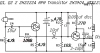
Here is a very simple,working and tested Fm transmitter circuit for newbies! It has built and tested by me and works a very long time using a 3.7 volt mobilephone battery! You may expect about 100-150 meters with a 400cm long antenna! Try more length for cover more range, the inductor can be an 8 turn,3.5 diameter of copper wire eg. Take a pen refill and wound 8 turns on it,remove the coil and solder it on the circuit, the second inductor that connected directly to the antenna is not needed plus adding a 22n (223) ceramic capacitor to couple the antenna will be useful to get rid of those frequency changing problem when touch or move towards the antenna, (i used the copper wires from a damaged transformer to make coils and it works fine) and i used 2xBC547 transistors,.. This is just a very basic fm tranmitter for newbies to work with..Good luck
 

Attachments

  • image_jm.png
    image_jm.png
    131.8 KB · Views: 463
I went ahead and redrew this schematic for you.

**broken link removed**

You do realize the original was drawn upside-down, don't you? Not wrong technically, just weird. Why would someone draw a circuit that way?

Anyhow, this looks a lot more believable than that 1-transistor circuit you posted earlier.
 
Funny; I found what I think is the original schematic for this circuit:

**broken link removed**

This was apparently modified (and redrawn, badly) by someone, possibly one of those notoriously error-riddled Indian circuit sites.

I'm curious: where did you find this circuit? Did you make any changes?

The original site seems to be reliable, and the author seems to have tested most of his stuff.
 
LTSpice is sure it won't work, too!
 
Which circuit above did you simulate? (I'm guessing the latter one.)

I take exception to Ziddik's comment: this circuit was definitely not designed by a "noob". Check out his website if you don't believe me.
 
Last edited:
Well, I simulated both of the circuits I posted here earlier in LTspice (attached below for your simulation pleasure).

Guess what? According to LTspice, neither one of them works! Now, I don't know if that's just due to some quirk of the software, or if I made an error somewhere (that hardly seems possible!). However, if Ziddik claims that one of them actually works, then I guess I'll have to take their word for it.
 

Attachments

  • Wireless mike.asc
    2.2 KB · Views: 183
  • Wireless mike 2.asc
    2.4 KB · Views: 159
Well, I simulated both of the circuits I posted here earlier in LTspice (attached below for your simulation pleasure).

Guess what? According to LTspice, neither one of them works! Now, I don't know if that's just due to some quirk of the software, or if I made an error somewhere (that hardly seems possible!). However, if Ziddik claims that one of them actually works, then I guess I'll have to take their word for it.

cz,
Look at the .IC [ initial condition] on the base of the 1st transistor.
If you start from zero V, the 4.7uF cap takes ages to charge up via the 100K, so the transistor is not biassed on until the Vb reaches ~0.65V.

To see the 'RF' you must select a time interval shorter than the wave form you want to see, look at the .tran values

Also you dont want to see the start up initial conditions.

I have also reduced the audio drive and made it 10KHz.

The right most image is the RF out
 

Attachments

  • AAesp02.gif
    AAesp02.gif
    42.9 KB · Views: 232
  • AAesp03.gif
    AAesp03.gif
    21.9 KB · Views: 200
  • Wireless mike_m1.asc
    2.6 KB · Views: 195
  • AAesp04.gif
    AAesp04.gif
    23.7 KB · Views: 204
Last edited:
The right most image is the RF out
Which if I interpret it correctly is a grossly distorted "sinewave" with a frequency of about 33Mhz.

All in all a truely horrible output for a radio transmitter which is supposed to be running in the VHF FM broadcast band.

JimB
 
Which if I interpret it correctly is a grossly distorted "sinewave" with a frequency of about 33Mhz.

All in all a truely horrible output for a radio transmitter which is supposed to be running in the VHF FM broadcast band.

JimB

hi Jim,
It is a horrible little circuit.!
My interest is only in the LTS simulation problem that 'cz' had with the circuit.
 
I second that. It will splatter interference over a wide band. Very anti-social.
 
if u have correct antenna shield and a well designed circuit the transmitter will not interfere or spread on all over the radio stations, i got crystal clear sound output when i added a 22000uf capacitor across the battery terminals because it cleared all those horrible distortion and hums! I had also tried low uf capacitors like 4.7uf,100uf..etc but they could't help.. Now i use the transmitter to connect to TV. Never connect the transmitter to a large antenna during adjust the transmitter because it will interfere with other stations! ..this is what i have tell u
 
FM radio stations all have pre-emphasis that boosts treble audio frequencies.
All FM radios have de-emphasis that cuts treble audio frequencies back down to normal so that hiss noise is reduced.
Your circuits do not have pre-emphasis so they will sound very muffled on an FM radio, something like a telephone or AM radio.

Your circuits do not have a voltage regulator so their frequency will change as the battery runs down.
 
ericgibbs said:
The right most image is the RF out
Which if I interpret it correctly is a grossly distorted "sinewave" with a frequency of about 33Mhz.

All in all a truely horrible output for a radio transmitter which is supposed to be running in the VHF FM broadcast band.

Ditto for what I observed (I ran Eric's simulation). Frequency was well below 40mHz. Some tweaking of the LC components could no doubt bring it somewhere into the 88-108mHz region.

And judging from the wave envelope, it looks to be more AM than FM, wouldn't you say? No doubt it works, as Ziddik claims, but it surely can't work well! As JimB points out, this is gonna splatter RFI all over the place.

Ziddik said:
this is just a basic transmitter so u can't use a powersupply to power this circuit! recharge the battery if it is low will be good!

BS. Why do you think you can't use this with a power supply instead of a battery? Of course, the real question is why you'd want to do that, but I'll leave that aside.
 
Status
Not open for further replies.

Latest threads

New Articles From Microcontroller Tips

Back
Top