Continue to Site

Welcome to our site!

Electro Tech is an online community (with over 170,000 members) who enjoy talking about and building electronic circuits, projects and gadgets. To participate you need to register. Registration is free. Click here to register now.

  • Welcome to our site! Electro Tech is an online community (with over 170,000 members) who enjoy talking about and building electronic circuits, projects and gadgets. To participate you need to register. Registration is free. Click here to register now.

Automotive 6 Volt Generator Transistor Voltage Regulator

Status
Not open for further replies.
Quoting myself:
wasJE3sW8D1TFCEbBaMd6gzvC4M0up4e-qxOiLt9O_axnjMl--wKpvOZ3A0WEXmlOcU1wQ5pgaH5PeFBM-5SGjksx9g4dX8TkIlpoAYhkF_FZO8yKT-F4ruQAq1x2oH-mFFzJMCZ

...
I'm thinking that the ideal is to get as close as possible to the regulator curve illustrated above. 7.5 volts at 0 amps, declining to 6.65 at 30 amps.
...
After studying this some more, I've come to understand that this is not the ideal. Rather, this declining characteristic curve is just the best they could do with a two-unit regulator. To protect generator against overloading, the regulator lowers the voltage supplied by the generator as the current increases. But this curve is only linear because one relay has to do two jobs: limiting voltage and current simultaneously. (BOSCH also made a better, more expensive, 3-unit regulator, but not for the VW).

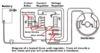
Taking the illustration (above) for example, the regulator is limiting this generator to roughly 30A x 6.75V = ~200 Watts load. But, if you back up to 15A it is capped to 7.25V which is only ~109 watts. Why not stay at 7.75V x 15A = 116 watts? It could stay at 7.75V until 200W/7.75V = ~26A, and then drop off steeply to stay in a 200W envelope. From 26A, it would drop at a slope of
(6.75 - 7.75) / (30 - 26) = -1 V / 4A​
So, we get something like this:
1601101357949.png

I think this has the potential to squeeze quite a few more coulombs out of the old generator without danger of overloading it.

I'm also thinking that the regulator should be customizable for a particular generator and battery. Two data points should be enough characterize it: unloaded charging voltage, and generator wattage rating.
 
Never underestimate these old Bosch engineers. They knew what they were doing.

The higher the batterry voltage, the less current is required.
 
Never underestimate these old Bosch engineers. They knew what they were doing.

Sure, but they were constrained by low cost requirements and 1950's (or older) technology.

The VW uses a two-unit regulator, but BOSCH made a three-unit regulator for Ford. I found this at MyClassicThunderbird:
1601183132857.png


"The current limiter protects the generator armature windings by limiting the maximum amount of current supplied by the generator. Any increase in current above the current limit setting, results in a decrease in voltage, but if the voltage decreases, the voltage limiter will not operate. Therefore, when the current from the generator reaches the current limit setting, the voltage limiter no longer functions. At this point, the current limiter assumes control. Like the voltage limiter, the current limiter performs its function by controlling the amount of current that is supplied to the generator field coils. When the generator output current becomes excessive, it energizes the current limiter coil sufficiently to open the points and, thereby, cuts off the voltage and resulting current going to the field. The resulting decline in field strength reduces the generator output and prevents excessive current from being produced by the generator, and thus protects the generator when the system load demand is high.

When the current limiter is operating, the voltage limiter contacts remain closed, and the current limiter contacts open and close at a rate of about 30 or 40 times a second."

The VW regulator only has two units, so it is a compromise design, with one unit regulating both voltage and current. Both designs have the cutout relay, but the Ford regulator has separate limiters for voltage and current. Presumably, the three-unit regulator was more expensive, and with the VW being the "people's car", cost was an overriding consideration.

I found this interesting comparison in Automotive Electrical Equipment, Kohli, Tata McGraw-Hill Education, Jun 1, 1983:
1601185518356.png

"It is also evident from Fig. 5.15 that in the case of the current and voltage system, the ampere-hour input to the battery in a given time is much greater when compared with the compensated voltage system. It is a very much desirable feature in the case of road vehicles..."
 

Attachments

  • 1601182770849.png
    1601182770849.png
    47.5 KB · Views: 238
Last edited:
It is a very much desirable feature in the case of road vehicles...
I am not sure about that for all cases since that extra charging power is being removed from the power to drive the car.
An old VW does not have a lot of power, so it is vital to be frugal with charging the battery.
 
I am not sure about that for all cases since that extra charging power is being removed from the power to drive the car.
An old VW does not have a lot of power, so it is vital to be frugal with charging the battery.
True. I have thought about a momentary cut-out. Many years ago I had a switch from J.C. Whitney under the hood of my Chevy that would cut out the clutch on the A/C compressor when intake manifold vacuum dropped low indicating hard acceleration. It worked really well in FLA where the A/C is pretty much always on. Get a little power boost for, say, passing, but short enough cut-out time that you would hardly notice a change in air temperature. But, that was on a V8. In a VW, you might have the pedal to the metal at all times, so I guess you'd need a time out or something. Maybe a boost button on the dash. But I wonder how much hp a 200W generator can really rob. (200W ~= 0.27 hp, + losses.) Would you really feel any effect from a boost button completely shutting down the generator? I have heard stories, probably apocryphal, that the old 25-horse VW buses would lose 5 mph of top speed when you switched on the headlights. With the 40 hp motor in my Ghia in the Colorado mountains, it's going to take a while to get up the hill no matter what.

Anyway, this is another argument for a programmable regulator. Different applications have different requirements. If I tend to make a lot of short trips at night, I'm going to want to prioritize fast charging. Or, if I'm on a long highway trip and it's raining and I have to run lights and wipers. Personally, with my driving habits and the old system, I find that I need to keep a charger handy in the garage to top up the battery from time to time. And, it is a concern on long trips when I want to charge my phone and listen to the radio and run the headlights, etc.
 
I am all for a programmable regulator too, as already mentioned, but based on my extensive experience, I will say that you will have a fairly long road ahead with this project.
 
Last edited:
True. I have thought about a momentary cut-out. Many years ago I had a switch from J.C. Whitney under the hood of my Chevy that would cut out the clutch on the A/C compressor when intake manifold vacuum dropped low indicating hard acceleration. It worked really well in FLA where the A/C is pretty much always on. Get a little power boost for, say, passing, but short enough cut-out time that you would hardly notice a change in air temperature. But, that was on a V8. In a VW, you might have the pedal to the metal at all times, so I guess you'd need a time out or something. Maybe a boost button on the dash. But I wonder how much hp a 200W generator can really rob. (200W ~= 0.27 hp, + losses.) Would you really feel any effect from a boost button completely shutting down the generator? I have heard stories, probably apocryphal, that the old 25-horse VW buses would lose 5 mph of top speed when you switched on the headlights. With the 40 hp motor in my Ghia in the Colorado mountains, it's going to take a while to get up the hill no matter what.

Anyway, this is another argument for a programmable regulator. Different applications have different requirements. If I tend to make a lot of short trips at night, I'm going to want to prioritize fast charging. Or, if I'm on a long highway trip and it's raining and I have to run lights and wipers. Personally, with my driving habits and the old system, I find that I need to keep a charger handy in the garage to top up the battery from time to time. And, it is a concern on long trips when I want to charge my phone and listen to the radio and run the headlights, etc.

If you're wanting fast charging and reliable electrics, then upgrade the entire system to 12V and fit an alternator - it will improve absolutely everything.

Many years ago a friend of mine had a Mini 1275 GT, and one cold winter morning the battery was completely flat - the engine wouldn't attempt to turn over at all. So we bump started it, when it started no problem.

Now my friend had fitted an ammeter to the car, which read +/-35A - now this was a cold winter morning, he had headlights on, heated rear screen on, and heater blower on - pretty well the highest possible loading. But even at that the ammeter was reading off scale charging, at more than +35 amps - and within only 2-3 miles dropped back to just over zero, the normal tickle charging of a fully charged battery.

That's the sort of performance you get from an alternator, MUCH better than a dynamo.
 
If you're wanting fast charging and reliable electrics, then upgrade the entire system to 12V and fit an alternator - it will improve absolutely everything.
...

That's the sort of performance you get from an alternator, MUCH better than a dynamo.
Absolutely, but it kinda gets back to the whole raison d'être of a classic car. I've had my Karmann Ghia 'vert since 1982, and in my younger days, I was keen to hot rod her. But one day a professional restorer of VWs and Porsches took me for a ride in his personal turbo Porsche (and I mean a ride!) and convinced me that she would never approach the performance of a Porsche that he had only invested around $20k in (mid-90s dollars). He convinced me to love her for what she is, and I have been slowly going back more and more to original stock. That said, as an engineer, I can't resist tweaking, and my charging system does not work very well, and there aren't a lot of good options for replacement regulators at this point in time. I'd like to fit new electronics in the old BOSCH regulator housing and make it work with my old 6V electrical system.

1601222522387.png

1601222582440.png
 
Hi, "CK3" Great to see the VW Photos! Yes the Electronic Voltage Regulators are far superior and now there are some ones you can buy for not too much that keep the Look. I really hear what you're saying about keeping a nice collector car "Original" It will be worth more too. Mine is getting the original 36 horse Engine Operated on right now and while that happens I have converted a 1971 VW Bus engine to 6 Volts and am running my first prototype 6 volt voltage regulator atop the 6 volt generator in the 1960 Beetle. The 6 Volt Electronic Reg Housed in the Bosch Mechanical reg housing was working perfectly until a screw came loose inside and blew it. I had to go back to a Mechanical 6 Volt Reg. and it was terrible with the lights on compared to mine. It would only run my Voltmeter up to 5.9 volts that's up front coming off the Ignition. The Electronic Reg will hold 6.5 volts with the lights on. It will go higher but I keep it set lower.
I had quite a time figuring out my blown electronic reg but in the end it was just wires. I have it going again. Here are some Photos:

Lights Off:
Lights Off.jpg

Lights On:
Lights On.jpg

Repaired 6 Volt Electronic Regulator inside:
6 Volt Electronic Voltage Regulator Lables 3.jpg


6 Volt E Reg Bottom View 4.jpg


1679cc VW Type 1 engine for a 1971 VW Bus modified to 6 volts running 1960 style Zenith NDIX 32 Dual Carbs and my 6 Volt E Reg in a Bosch Housing:
6 volt 1679cc Inatalled With Electronic Reg..jpg
 
Last edited:
Hi Tried some Ideas today with the Prototype in the car to see if I could get it charging better when first started up from cold. Implemented the following changes but still using the coil power at start up instead of the Transistorized (Start Circuit) (Which failed first day in the car) but here is that schematic. It still was a little fussy about holding good voltage cold but it does start charging ok, and regulates well on the highway and with headlights. (Changes were made to the supplies Isolating them from D+ with diodes, that keeps startup power usage at startup to a minimum!)
6 Volt Reg_1_2020.JPG

Now this afternoon something dawned on me looking at the first Schematic and it was, I didn't have the "E" Comparator's (Regulates Gen Voltage) input configured ideally. So here it is, a pretty major design change to the above Schematic about 8 components eliminated. Basically the reference supply is gone and the reference voltage now comes from the output of the "I" comparator. (Gen Current Regulator), Also the (pin 2) input Voltage measurement from D+ will be with a 2 volt Zener Diode. (It should help keep the output of "E" pin 1 high during startup.) Tough High Gain Power TIP3055 and TIP2955 BJT Transistors are on order for this new design's (Start Circuit). A Low Forward Voltage Drop 1N5817 diode can be used to isolate the Unregulated Power Supply from D+.
6 Volt Reg_1.1_2020.JPG
 
Last edited:
Modifying a 12V alternator to work at 6V is labour-intensive work. You'd either rewind the stator coil or add a hefty step-down ( switching) voltage regulator in series to the battery. An alternator with an internal voltage regulator may need to be redesigned for 6V operation.
 
Modifying a 12V alternator to work at 6V is labour-intensive work. You'd either rewind the stator coil or add a hefty step-down ( switching) voltage regulator in series to the battery. An alternator with an internal voltage regulator may need to be redesigned for 6V operation.

Surely for an external regulator type alternator as used here, it would be a matter of just regulating the output to 6V instead of 12V without any modifications to the alternator? It would simply be a lower excitation voltage on the armature.
 
Surely for an external regulator type alternator as used here, it would be a matter of just regulating the output to 6V instead of 12V without any modifications to the alternator? It would simply be a lower excitation voltage on the armature.
Exactly.
The current rating is still the same, so half the total power it would be capable of on a 12V system, but eg. 80A is still 80A.

It it had an internal reg, you would have to be replaced or substituted for an external one.
 
In the world of Air Cooled VW's there is a need for a good 12 Volt Alternator that is only 90mm in diameter like the 6 Volt generators (45 Amps) used in them to 1965, The problem is the VW generators starting in 1966 still 6 volts went to something like 105mm in diameter then in 1967 still 105mm it became a 12 Volt generator (25 and a 30 Amp) then in 1973 105mm 12 Volt Alternators (50 Amps). VW Enthusiast dedicated to maintaining Original looking cars are stuck with 6 Volt systems for cars 1961 and earlier because the 90mm generator stand is part of the engine block. 1961 and later VW can be easily upgraded to 12 Volt Alternators as the generator stand became removeable.
The 6 volt VW's have poor headlights and with no very good 6 Volt LED H4 Headlight lamps for them exist. Going to 12 volts and the additional Amperage of an Alternator solves lighting issues, Starting issues and opens up the options for better sound systems in the cars. I have installed a later engine in my 1960 Beetle while I rebuild its Original engine and could have easily given it a 12 volt Alternator however, so I would have reverse compatibility I downgraded a 12 Volt engine to 6 volts using a 6 volt generator and generator stand etc and a modified flywheel and fan.
Dual Port Fan 356 Fan copy.jpg

Later model 200mm clutch flywheel with a 6 volt ring gear: (Original flywheel had a 180mm clutch.)
6 Volt Flywheel MOFOCO (2) copy.jpg
 
Last edited:
Ok so I have the Prototype 1-A installed in the car. It's working as it should. The 3055-2955 Start Circuit works perfectly. Voltage Regulation is precise. It took a couple of changes, the design is not as perfected as I would like but it does work. (Adjustments are a little too sensitive.) Left Out the Big Field Resistors and the .1Uf (Because I couldn't find it) on the Current IC to Voltage IC's Reference input Feed, which would stop dropout glitches! (Current limiting seems to have an improved threshold over all the other designs ). Now operating with Two 2 Volt Zeners in series to D+ and 5.1 Volt Voltage Reference Zener on the "E" IC's input. I have some Ideas on improving this design, however the Pull Up Design in Prototype 3 would probably be a wiser starting place.
(In this Prototype 1-A all Resistors and Diodes were eliminated from the circuit board which made assembly a lot easier and provides more flexibility with design changes.) (Also the Reference supply was eliminated, Reference Voltage is now supplied via the "I" IC's output.)

6 Volt Reg_1-A.JPG

6 Volt Regulator 1-A.jpg


6 Volt Voltage Regulator 1-A.jpg


6 Volt Regulator A-1 Top View'.jpg


6 Volt REG Bottom A-1.jpg
 
Last edited:
Hi, "CK3" Great to see the VW Photos! Yes the Electronic Voltage Regulators are far superior and now there are some ones you can buy for not too much that keep the Look. I really hear what you're saying about keeping a nice collector car "Original" It will be worth more too. Mine is getting the original 36 horse Engine Operated on right now and while that happens I have converted a 1971 VW Bus engine to 6 Volts and am running my first prototype 6 volt voltage regulator atop the 6 volt generator in the 1960 Beetle.
Very nice! I've got the (more or less) original 40-horse from my '64 Ghia rebuilt, broken in, and stored. I was lucky enough to have a '66 1300 lying around, and that is now rebuilt to 1600, but otherwise stock. Works out nice, because both engines are 6v, and complete, so I can swap them in an afternoon. That 1600 single-port is more powerful than I expected, which is nice in the CO mountains. It's also handy having two of everything so I can debug by swapping, or borrow a part (or the whole engine) when needed.

IMG_20191001_152111_DRO.jpg
 
You're a little ahead of me! Same going on here only with a 36 horse still in pieces.
Took the beetle out today and the generator light came on at just over 70. Weird though the voltage was stable right at 7.0 volts!
Seems to repeat with speed.
 
Took the Beetle out for a test drive again today and for sure it gets a Generator Warning light at high speeds. One thought I had is the current IC is causing this, there is a bit of a voltage glitch when the warning light first comes on. Need to find that .1uf cap to the Current IC output. Maybe it will need the field resistor too. Maybe I need to put it on the SCOPE!
(For the generator light to come on, the black wire from the emitter of the TIP 3055 start circuit which connects to D+ would have to be losing it power from the armature and seeing ground. I don't see how this could happen and not have more of a disruption to the output voltage though. More likely the air draft behind the dash is shorting something!

(January 16, 2021 Update)
While driving around in the Beetle today this Prototype 1-A LM317P Voltage regulator failed then came back intermittent. I was able to trace the culprit to the 10 Turn 1K Potentiometer used. I had run out of the previous ones and have been using a different type, I have found that at least this one is flakey and has a open spot that sometimes shows up.
Also after getting it working I tested the current limiting circuit and it's Just not working! It's either just on or off regardless Headlights on etc...

The Good News is I installed the Single IC LM393 Prototype and it's working, it does have a very narrow range where it does current limit with headlights quite nicely too. It's design needs to be changed to increase the current limit adjustment span to be nicer to set-up also It has the same Pot type that may be a problem, as well as the latest prototype with the LT-6700. Probably should eliminate the use of that type of pot.


(January 21st, 2021 Update)
I am going to try a design change on this last LM311P Prototype 1-A calling it Prototype -1-B or something.
I plan to change the current potentiometer then rewire the LM311P inputs to measure B+ as below. If this works it should eliminate the cutout diode voltage drop about .3 volts and hold a higher stable voltage with the headlights on.


Prototype 1-A
6 Volt Reg_1-A.JPGProblem 10 Turn Pots.jpeg

Prototype 1-B
LM311P Prototype 1-B.jpeg
 
Last edited:
Status
Not open for further replies.

Latest threads

New Articles From Microcontroller Tips

Back
Top