Continue to Site

Welcome to our site!

Electro Tech is an online community (with over 170,000 members) who enjoy talking about and building electronic circuits, projects and gadgets. To participate you need to register. Registration is free. Click here to register now.

  • Welcome to our site! Electro Tech is an online community (with over 170,000 members) who enjoy talking about and building electronic circuits, projects and gadgets. To participate you need to register. Registration is free. Click here to register now.

Automotive 6 Volt Generator Transistor Voltage Regulator

Status
Not open for further replies.
I got my hands on some TL431 Voltage ref's that are much more accurate than Zener Didoes and I found a Calculator for figuring resistor values to set them up relative to ground which worked on Voltage Comparator input pin 2 but is there a way to use the TL431 to replace the 12 volt Zener to D+ as it is in the Schematic just above. Would it work with it Cathode directly to D+ and it's Anode to pin 3 and the 500 ohm resistor to ground. Can it's reference voltage be set with two resistors between Cathode and Anode?

Like this:
LT431.JPG
 

Attachments

  • Screen Shot 2020-03-31 at 2.00.22 PM.png
    Screen Shot 2020-03-31 at 2.00.22 PM.png
    148.6 KB · Views: 184
Last edited:
It may work, if the resistor values are high enough?
There will always be some current through the ref circuit at any voltage, unlike with a basic zener.

Just make sure the voltage across the 500 Ohm due to the other resistors is well below the comparator reference!
 
The arrangement you show should result in a voltage on pin3 which is a preset voltage below 14.5V, not a preset voltage above ground. Is that what you intend?
 
Yes "alec_t" Ok good thanks "rjenkinsgb" I will mock it up and see if its better than the zener which varies quite a few mv with voltage increase. If I make the voltage drop Cathode to Anode 10.5 volts with R1=3200 ohms and R2 1000 ohms then at 14.5 volts out of the generator on D+ the comparator reference voltage can be >4 volts. Resistor network current will be 2.2ma and the IR across the 500 ohm will be 1.2 volts at a D+ voltage of 10.5 volts,. Well below comparator threshold which will be 4 volts, Thanks!
12 volt Regulator:
12VoltRegulator.jpg
 
Last edited:
If you get it right, it will be a lot better than a Zener.
Zeners are pretty bad, when there is not enough current through them (~60% of the rated current)

I am not too sure how robust the TL491s are for such a rugged envorinment.

The only question is where you need that sort of accuracy here.
 
Well, the comparator switches with only 5mv difference. It may clear up about 1/4 volt shift in D+ voltage between 2000 rpm and higher rpms that the earlier designs have.
 
Ok the series drop works, I measure 10,6 volts with about 5mv change per 5ma at the 500 ohm resistor. These are TL431 and I bet they are the 70-80'c ones! They will be ok but marginal. The generator won't get that hot but the engine block runs 80'c to 100'c they will be somewhat away from engine heat probably epoxied to the Voltage Potentiometer and Circuit Board likely less than 50'C. Also the 12 volt regulator mounted under the back seat in later model VW Beetles.
 
Last edited:
I don't understand why you have two TL431"s in the post #24 circuit (?).
All you need is one properly placed.
 
Thanks for the post "crutschow" Earlier in the thread "rjenkinsgb" came up with the Idea of using a zener in series with the inverting pin to the Dynamo Output to keep voltages within the comparator voltage parameters. It also increased sensitivity and accuracy . I am just. playing with the TL431's now to further improve Dynamo output voltage stability. They are a bit of.a pain and for sure just one TL431 could be used to establish the Reference voltage for the Non Inverting and just use resistors on the Inverting to sample Dynamo Output Voltage.
LT431 Boards.JPG
 
Last edited:
Just got the 12 Volt Electronic Dynamo Regulator working testing it with Batteries. I don't have a 12 Volt Generator on a Engine to fully. test it. It consists of a 2 1/2" Tall Heat Sink for the Cut Out Diode with the Current and Voltage Control Board at the bottom and TL431 boards attached.


Front View:
12 Volt Reg Front View.jpg


Side View with Hook-up's U=Unregulated Supply, S=Current Sense, Delta=Ground and Hidden behind the Red Wire is a D+ Terminal.
12VoltReg Side View Hookups.jpg


Bottom View Current IC "I" on top, Voltage Control IC "E" lower: (Yellow=DF, Red=D+, Blue=Gen-Lamp and Black=Ground)
12 Volt Electronic Voltage Regulator BV.jpg


Note StartCircuit Transistors are mounted near the top of the HeatSink with their resistors. MOSFET mounted near the bottom with a clip.

Back View:
12vReg ISO View Back and Side.jpg
 
Last edited:
The TO-92's TL-431 came and I made a Power Supply for testing. It works quite well.
The regulator wiring involves 1(connecting the grounds) and 2(the Supply + Output to B+) 3(Gen. lamp from Supply Output too to the blue wire) and 4(the load) I use a 6 volt LED tail Light in series with a 6.4 volt Zener diode Supply + Out to DF.

Regulator Power Sche.JPG
 
Last edited:
Hello everyone.

I recently spent too much time overhauling my collection of old electo-mechanical BOSCH 6V two-unit generator voltage regulators. Even with a lot of tweaking, I've decided that I'm dissatisfied with the efficiency I can get out of them. I want to get all the power that I can (reliably) get from my generator, because I use my headlights as daytime running lights a lot, and I must have my phone charger when I'm on a camping road trip, and I just can't seem to get too much out of the 7V 45A generator.

I looked at a couple of solid state regulators on the market:
I really wish they would publish data sheets on these!

Also, I'm running an Optima REDTOP battery, which specifies "Recommended charging information: Alternator: 6.65 to 7.5 volts, no amperage limit." (https://www.optimabatteries.com/en-us/support/charging/charging-tips), which is a little different than the normal voltage regulator specs., so I'd like to be able to customize the output a bit. I don't think any of the off-the-shelf units are adjustable.

So, I'm thinking of building instead of buying. The is Wolfsburg West one is $185.00, and I think I could cobble something together for a lot less than that! Plus, I have a few old regulators I could use for housings and other parts.*

So, that's how I became interested in this subject. But, before I jump right in and start building from the schematics in these pages, I have some half-baked ideas of my own. I happen to work with microcontrollers, so my first thought, of course, is "Why not go digital?" How hard could it be to borrow some of the power handling circuitry from Danwvw's design or the "BOSCH" design and put a MCU in control? There are inexpensive MCUs with A/D, D/A, PWM, whatever you want.

I found this on TheSamba.com:
1600753659586.png


1600753721202.png


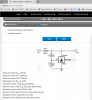
Wiring of a DC generator with a TA regulator (two-unit regulator)
The most frequently used type of regulator is the two-unit regulator with declining characteristic curve (illustration)
...
The higher the current, the lower the voltage supplied by the generator. This protects the generator against overloading.
(emphasis mine)

I'm thinking that the ideal is to get as close as possible to the regulator curve illustrated above. 7.5 volts at 0 amps, declining to 6.65 at 30 amps. Cut out when the generator is putting out less than 6.65. Put some smarts behind the idiot light.

Thoughts? I'm new here. I hope I haven't just accidently stepped into some analog-vs-digital holy wars!

- Carl

* And besides all that, the ones one the market all seem to be sold out.
 
Last edited:
If you use an MCU, you can have far more precise control of output voltage & monitor the true charge current, rather than just shutting off of the dynamo if the voltage is below a fixed threshold.

With suitable sensing and power switching it should work very well.
 
There is no question that I would use a CPU if I were to build a regulator like this.
The main problem here is to get the charge cycle started so the regulator can have power.
The second issue I see with a CPU is to protect and filter everything so that the 'dirty' feedback will actually make sense.
All doable but bei g a design engineer, I can say that nothing is ever as easy as you think.

The OP deserves a medal for all his effort and persistsnce to get something working.

Let us know how it turns out.
 
Can't I just use the car battery?
That would be the "normal" operating method; I'd have the MCU modulate the generator warning light current rather than connect it to the dynamo direct, then sense that being powered to switch on the regulator electronics.

Once the unit is on, the main power can come from the battery to power the field control FET.
 
Those solder joints are going to crack in very few hours of run time. Support all of the connections so they don't short out your generator or you'll have a really bad day.
 
That would be the "normal" operating method; I'd have the MCU modulate the generator warning light current rather than connect it to the dynamo direct, then sense that being powered to switch on the regulator electronics.

Once the unit is on, the main power can come from the battery to power the field control FET.
That sounds good. I'm thinking the MCU could go into deep sleep (a couple uA of current draw) until it gets an interrupt from terminal 61 (generator charging warning light connection) going high. I was already thinking of taking direct control of the warning light. That would allow some possibilities like
  • steady light on indicates 0 generator voltage (e.g., key on but engine not running, or engine is running but fan belt broke)
  • flashing light indicates low battery voltage
  • maybe even a special mode that flashes out stored problem codes
With the original regulator I guess it is possible to run the car with no battery at all; push started. I don't know if I want to support that use case; I could see where getting the generator started and all that could get messy; regulating the voltage might be difficult, too, without the battery to smooth things out. But, maybe it is worth considering. I guess car batteries can go open circuit, or (more likely) battery terminal connections go bad. At least, it should do something reasonable if the battery connection goes open circuit while things are up and running.
 
Last edited:
Status
Not open for further replies.

Latest threads

Back
Top