Continue to Site

Welcome to our site!

Electro Tech is an online community (with over 170,000 members) who enjoy talking about and building electronic circuits, projects and gadgets. To participate you need to register. Registration is free. Click here to register now.

  • Welcome to our site! Electro Tech is an online community (with over 170,000 members) who enjoy talking about and building electronic circuits, projects and gadgets. To participate you need to register. Registration is free. Click here to register now.

Automotive 6 Volt Generator Transistor Voltage Regulator

Status
Not open for further replies.
I am not fully following why the circuit will not work with single Q.
The lamp will turn on and stay on via the be junction (and of course the 33Ohm resistor). why would it just flash once?

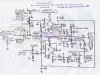
Assuming the current you calculated into D+ is ~3.5A, the base current would have to be 3.5/(hfe+1)
which is roughly 318mA. (assuming hfe = 10). I am not sure if your lamp would draw that amount of current on VB - 0.6V-D+ ?

But you have a point in that this could settle at a base current that is not enough for the lamp to be visibly glowing. D+ could rise enough so that the lamp current is too low to be visible.
Perhaps one could see a flash, initially but probably not as the transistor is too fast and D+ would rise very quickly.
 
Last edited:
That's what I was thinking but Knowing how to use the hfe is something I was avoiding. Yeah I calculate Lamp current to be 147ma thats 32 ohm hot filament + 2.5 ohm varistor + 1.6 ohm armature = 36.1 ohms. Using 5.7v that's 147ma a one transistor design the light would see 5.7 volts for an instant then almost nothing. I bet it will Oscillate or just get hot and not be enough to boot up the Armature.
 
Does a lamp current of 147ma mean that:
Given @ gain 6:
6*.147=.882 amps
1.6ohms*0.882=1.4 volts only on the armature
transistor is going to see the rest 6-1.4 about 4.6 volts
watts = 4.6 volts * 0,882 amps 4 watts for the single transistor design.
Note Just measured lamp current on my car it's 151 ma thats about 37 ohms hot!
 
Yes, that is almost correct. You need to add the base current to the collector current so in your calculation, add another 0.147A (Ie = Ib + Ic). But either way, it looks bleak.
You could go for a Darlington setup but then the voltage drop will be 0.6 * 2 and there is only 5-6V to play with.

BTW: I corrected the formula /calculation of my previous reply. It should be Ie = Ib*(hfe+1). For transistors with a high hfe, the +1 make no difference but for a transistor such as this, with a low hfe, it is important.
 
Last edited:
Still thinking about this... If you pursue this powering of the armature, then I think the better way will be to have a transistor that saturates. The transistor will then only have ~0.2V on Vce and the power dissipation will be minimal.

That is will not be possible with the NPN emitter follower design. You would have to change to a PNP transistor and pull the base low with a NPN driver transistor in front of it, controlled by the lamp current.. ( I do not have a means to draw but you can figure it out easily).

Another question is whether powering that armature like this will influence the residual magnetism of the field coils. I have no idea.

Edit: The above is flawed as your lamp will not work unless there is a separate ground path for it's current(The NPN driver emitter has be grounded) , which we do not have without wiring mods, which defeats the purpose of what you are trying to do. Dang!
 
Last edited:
Actually it's a good way to polarize a generator If the Field is Grounded? But I don't think it's the best way to start up one but it works! So does just grounding the Field good. I grounded the field with a screwdriver on a screwed up mechanical reg first try with the gen on the bench engine and it blew out my High Beam element in that 7" Round in a heartbeat without a battery on it. I switched Headlight elements for the load and got the mechanical reg working but the voltage was pretty erratic. Switched to electronic reg in the video and that worked great!
 
Last edited:
The BU2508 NPN Power Transistors arrived and I did some testing using a Gen Lamp and a HeadLight. It works but not full On. I have some GE D44H11 High Gain NPN Power Transistors on Order that I am thinking may do better.
BU2508_Test.JPG

Headlight 1.5 ohms calculation from Lamp Wattage (Test circuit current calculations with IR Drop across .33334 ohms in series with the headlight shows the headlight is more like 1.13333 Ohms)
 
Last edited:
Another "datasheet" that does not give us a Ib max. The only reference to base current is a condition of Vbe max given Ibe = 0.8A.
 
I too noticed some don't show it. I think I saw it at 0.8A somethere.

Today I tested the BU2508 on the Engine and It does work however it requires a little more revving than the Un-Regulated resistor to 12 volt arrangement I have been using on the Test Bench Engine with the Prototype 1 Electronic Voltage Regulator. (Note! Prototype 1 has flaws in its design in that it doesn't gate the MOSFET "on" until the Reference Supply is powered which only can happen from D+ voltage.) (Note! Prototype 2 in the car although gated with just.a resistor to the Un-Regulated Supply voltage may be gated off by the E comparator due to the same Reference supply Design flaw.)
My testbench engine with a 6 volt generator is still using a 12 volt battery, starter and coil. Actually I don't have a spare 6 volt battery so I rigged the following circuit using Hi & Lo Beam Halogen Head Lamp filaments in parallel to drop the voltage to 6 volts for the test. (I got 4 volts!)

Before the engine starts with the power on The Gen Lamps light nicely and there's 4 volts at the B+ on the Regulator with just 1.8 volts on D+ then
After starting the engine and revving it the voltage begins to build at D+ but not until it hits 5 volts does the generator start charging.
The regulator still manages to regulate D+ nicely around 7.6 volts revved without being loaded to ground now. Gen lights working nicely with just a little glow but remember they are seeing the difference the 12 volt battery and D+.

My conclusion is that these generators using Prototype1,2 build at least 5 volts on D+ (about 3.125 amps flow) before charging kicks in solid. I have seen this D+ go to 5 volts on the cars 6 volt generator too with prototype 2 If I wait a couple of weeks without starting it then try it on a cold morning.

BU2508_EngineTest.JPG
 
Last edited:
Today setup and tried the following two transistor circuit powering just the Electronic Voltage Regulator internal Supplies. Made modifications to Prototype 1 Ie... Moved Ref Supply power from D+ to U (unregulated supply)
This is it! What we have been looking for. Starts up easy not much revving of the engine at all. Holds in better too. The start circuit could be added to the other prototypes as a final solution to start-up that doesn't require switched 6 volts. Quiescent current draw is less than I can measure. Prototype1 Updated!
(Note! Testing shows that the Electronics inside Prototype 1 won't kick in with just 5 volts supplied, takes 6 volts on the un-regulated before it will switch on the MOSFET!)

Note! (Blue Key off voltages, Green Voltages are engine stopped key on, Orange Voltages are engine running gen. charging.) (All Voltages relative to ground!)
2QSC_EngineTest0001.JPG
 

Attachments

  • Prototype1Updated.JPG
    Prototype1Updated.JPG
    338.2 KB · Views: 187
Last edited:
As I am going to be building a Voltage Regulator just made to install into a mechanical regulator housing and using the above start circuit here is a Schematic and Layout for the start circuit tested above:
2QLayout.JPG


As Tested:
2QStartCircuitInstalled.jpg
 
Last edited:
That sounds good. It will be interesting.
BTW: I take my hat of to you for for your dedication and persistence with this.

Regards
Bernt
 
Thanks. Tell me more about your L3500 so it's been converted to a 12 volt gen? What about that reg is it an old original mechanical original part for the L3500? What is the 12 volt gen from a later year model?
 
Have you seen pictures of a L3500?
It is 12V. Not converted.
The generator is a Bosch 160W unit 10A.
The regulator is also an original one but I think it is broken. The cover is missing and everything is covered in grime and corrosion.
I have just finished fabricating vital coolant system piping and restored the rusted out thermostat and housing.
Next is the starter motor and then I will try and start it. It last ran in 1976.
Big project.
 
Wow 12 volts in 51! I will have to research the L3500, Love. projects like trying to start somthing that has not run in 50 years! Too bad you don't have the cover for the reg. I wonder if it's the same as the later or other models used. It would be a great application for stuffing some electronics into. Usually old mechanical regs can be coached to work a little if the Generator is still good. I wonder about the Generator if it's good. I know on mine I can see small DC and AC voltages on my Volt Meter when I spin a good one. Ground the field Measure the Armature no power just the volt meter give the gen a spin by hand. Maybe leave the belt off the Generator if possible for First Start, I love First Start Engine videos on U-Tube. Bet no one ever did one for the L3500!
If it's been garaged all that time and no water got in the engine it should still turn over. What usually happens is the rings rust to the cylinders so it will at lest need a ring job. Just as well rebuild it if it won't turn over. Is it a diesel?

 
Last edited:
Very nice. I am doubtful that my engine will start. I think the compression is very low.
 
Last edited:
You may have to pull it to start it. I never got the Beetle to start again after the Video. Not until I did all kinds of stuff trying to find the problem. Which turned out to be a blockage at the fuel shutoff reserve valve attached to the Gas Tank. In the process I rebuilt the carburetor and the fuel pump and removed the fuel tank and cleaned an painted it and installed new fuel hose and rebuilt the pet cock. But the reason it wouldn't run originally turned out to just be the blockage at the fuel shutoff pet cock valve.
PetCock&Beer.jpg
 
Last edited:
Yes, that can happen. At the end of the day, once you start with this stuff, it never ends until basically everything has been done.
 
Today I drew this up as a possible design for a 12 Volt Generator Voltage Regulator. It incorporates the Zero Battery Drain BJT Transistor Start Circuit and A different way of handling current regulation. Basically the Voltage and Current IC's Outputs are in Parallel. I am not sure this would work however I am guessing. it may work better. Your thoughts on this Parallel Idea or any comments please?
12VoltRegSchematic.JPG
 
Last edited:
Status
Not open for further replies.

New Articles From Microcontroller Tips

Back
Top