Continue to Site

Welcome to our site!

Electro Tech is an online community (with over 170,000 members) who enjoy talking about and building electronic circuits, projects and gadgets. To participate you need to register. Registration is free. Click here to register now.

  • Welcome to our site! Electro Tech is an online community (with over 170,000 members) who enjoy talking about and building electronic circuits, projects and gadgets. To participate you need to register. Registration is free. Click here to register now.

Analogue Dub Siren

Status
Not open for further replies.
Hi Rorut,

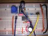
Below is a schematic which you may like to try. The values of the capacitors are not critical but the two 100nF decoupling capacitors should be ceramic or polypropylene types and need to be mounted with short leads and as close to the opamp supply pins as possible.

Also if you can make the layout follow the layout indicated on the schematic that will help prevent oscillations. The order of the 0V line connections are particularly important.

spec

2017_01_12_ISS1_ETO_DUB_SIREN_AMPLIFIER_V10.png
 
Wow, that was fast! Cant wait to test it. But can I use 1nF instead of 22pF? Only one I did not have. Thank you very much!
 
Wow, that was fast! Cant wait to test it. But can I use 1nF instead of 22pF? Only one I did not have. Thank you very much!
No probs Rorut,

No, afraid, 1nF is too big- just leave the 22p capacitor out.

The 47 Ohm resistor and 22p capacitor do not have any effect on the fundamental operation of the amplifier. They just form a low pass filter to keep out high frequency signals in the air: radio, TV etc. I once made a preamplifier that was an excellent radio receiver.:D

Likewise, the 47 Ohm resistor in the output has no effect on the functioning of the amplifier. It is just there to isolate the amplifier output from any capacitive and inductive loading on the output. This also helps to avoid frequency instability and other unwanted effects.

This amplifier is DC coupled so we can test the gain at DC.

spec
 
Last edited:
Hi again Rorut,

When you have built the amplifier of post #101, you may like to follow the test procedure listed below.

spec

(1) FREQUENCY STABILITY
(1) Set the amplitude potentiometer to the bottom of its travel.
(2) Connect your AC detector to the output of the amplifier.
(3) The AC detector meter shall indicate around 0V
(4) Slowly rotate the amplitude potentiometer to maximum
(5) The AC detector shall indicate 0V throughout the full range of the amplitude potentiometer settings.
(6) Set the amplitude potentiometer to minimum

(2) GAIN
(1) Connect the positive terminal of a 1.5V or similar battery to the input of the amplifier and the negative terminal to the 0V input.
(2) The voltmeter shall indicate close to 0V
(3) Connect one lead of a voltmeter to the output of the amplifier and connect the other lead to the OV output of the amplifier.
(4) Rotate the amplitude potentiometer
(5) The output voltage of the amplifier shall increase (if you have a log potentiometer, fitted the output will increase very quickly over the first few degrees of rotation)
(6) Reverse the connections of the battery and repeat the procedure above.
(7) The output of the amplifier shall decrease (go negative)

NOTE; 'shall' is test specification speak for 'must happen'
 
Last edited:
Hi Spec,
almost done.
one question, is the +-12v another PSU? should i connect the + from that to pin 4 and - to 0?
 
Hi Spec,
almost done.
one question, is the +-12v another PSU? should i connect the + from that to pin 4 and - to 0?
Hi Rorut,

I was thinking that you would be using two 12V batteries. If so, call the batteries battery #1 and battery #2 and do the following:

(1) Connect the negative terminal of battery #1 to the positive terminal of battery #2.
(2) The junction of the two batteries will be the OV POWER LINE to the circuit.
(3) The positive terminal of battery #1 will be the 12V POWER LINE to the circuit.
(4) The negative terminal of battery #2 will be the -12V POWER LINE to the circuit.

Connect up the batteries separately from the circuit as a power supply and run three wires twisted together to the circuit. Make the power wires a decent thickness and no more than about 12cm long.

spec
 
Last edited:
Frequency:
AC on multimeter over capacitor (resistor,diode,capacitor) gives 0.004v and nothing happens when rotating the pot.

Gain:
Connecting a 1.5v battery, positive to input and negative to 0:
1. Multimeter on DC first indicates o.oo4v the goes to -10.9v, changing polarity, battery positive to 0 and negative toinput gives 11.3v and begins with 0.006v.
2. Same thing with AC on multimeter (not sure which one to use in this case, dc or ac so did both), starting at 0 and when rotate the pot it increases up to about 1.9v but never stays there it goes back to 0. jsut showing some more voltage during the rotate.

Not using the second supply I get 10.4v over the capacitor (resistor,diode,capacitor)

:)
 
Last edited:
tested with siren connected and it sounds. Potentiometer now works :) not very much gain when rotating but seems to be much more stable than before and it actually goes from silent to louder.
Is it possible to increase gain more? Or did we reach the limits?
But it did not work with only one supply. Is it possible to use it with only one source?
 
Last edited:
Video:
**broken link removed**

Domt know if I did any progress in breadboarding but tried to keep the components closer :)
 

Attachments

  • IMG_4264.JPG
    IMG_4264.JPG
    1.9 MB · Views: 141
Well done Rorut- pour yourself a pint of beer.:)

I do not want to put the kibosh on things by speaking too soon, but everything looks good so far.:D

The gain of the circuit of post # 101 is 11 which, because of the ear's logarithmic response, will not sound that much louder.

No the limit of the gain has not been reached but if you need a lot of gain another opamp will be required.

As before the gain is defined as A = 1+ R2/R1 so to increase the gain you can reduce the value of R1 (in theory you could also increase the value of R2 but best stay with the 10K resistor)

Give the amplifier a run with R1 = 470 Ohms to give a gain of, 1 + 10,000/470 = 21.28 (note commas are separators not decimal points as I think you use)

Keep your fingers crossed.:)

If that works put a 10 Ohm resistor in series with a 5K or what ever potentiometer so that you can have variable gain, but keep the layout compact (no long wires).

Do you think you could get some low-value capacitors: 10p, 22p. 47p, 100p, 220p, 470p some time?

spec

Well thanks to you! Thank you very much!
WIll try with a variable gain
But it feels a bit impractically to use two PSU ? Is there a way around this?

I ordered a box with some ceramic capacitors a couple a weeks ago, think the lowest value was 100pF. Maybe buy some more of that values you asked for above .
Again, very thankful for all help!
 
Well thanks to you! Thank you very much!
No probs- I am just glad that we have got some clean amplification now.:)
But it feels a bit impractically to use two PSU ? Is there a way around this?
Yes. hopefully, we will end up with a single supply version to do what you want, but I suspect that a move to strip board and an optimum layout will be required.

If you need a high gain it may be necessary to go for a different opamp.

Do you have an eight-pin turn-pin chip socket so that we can roll (change) opamps easily?

I ordered a box with some ceramic capacitors a couple a weeks ago, think the lowest value was 100pF. Maybe buy some more of that values you asked for above.
That will be handy for your future electronic projects and also to put the finishing touches to this project.

spec
 
The circuit in post #101 has a gain of only 1+ (10k/1k)= 11 times which is not much. Increase the value of R2 for more gain. The input pot is a volume control, not a gain control. It is easy to properly bias an opamp so that it does not need a dual polarity supply.
 

Attachments

  • Opamp biasing.png
    Opamp biasing.png
    15.4 KB · Views: 141
No probs- I am just glad that we have got some clean amplification now.:)

Yes. hopefully, we will end up with a single supply version to do what you want, but I suspect that a move to strip board and an optimum layout will be required.

If you need a high gain it may be necessary to go for a different opamp.

Do you have an eight-pin turn-pin chip socket so that we can roll (change) opamps easily?

That will be handy for your future electronic projects and also to put the finishing touches to this project.

spec

Sounds great. I will just test with the gain pot like you suggested before moving to strip board.

Would be great if there is an opamp with higher gain that can be used in the same circuit? But maybe it need adjustments to everything doing that?

Yes I have a 8-pin socket that makes it easy to plugnplay the opamp.

Should I get to the electronics shop today for some specific components? Can visit a local store before weekend and try to get some if needed.

That looks better, but breadboards are not really suitable for high-gain or high-speed circuits: afraid it is simply a physical thing.

By the way, I forgot to ask: have you got any strip-board as shown @ https://www.electro-tech-online.com/articles/core-components.782/

spec
I have two types of stripboard. One like the one you linked with long rows from side to side and one with 3 connected holes connected. Similar to pictures

Forgott to mention but I used a linear trim pot, did not have a log trim pot for the volume (that I first thought was the gain)
 

Attachments

  • IMG_4269.JPG
    IMG_4269.JPG
    13.8 KB · Views: 134
  • IMG_4270.JPG
    IMG_4270.JPG
    15.4 KB · Views: 119
Last edited:
The circuit in post #101 has a gain of only 1+ (10k/1k)= 11 times which is not much. Increase the value of R2 for more gain. The input pot is a volume control, not a gain control. It is easy to properly bias an opamp so that it does not need a dual polarity supply.
Spec told me to stay with value for R2 and that in theory it could be changed to increase. I dont know why? Stability on breaboard?
 
Last edited:
Spec told me to stay with value for R2 and that in theory it could be changed to increase. I dont know why? Stability on breaboard?
R2 is a feedback resistor which connects to the inverting input of the opamp and thus forms a feedback loop.

Feedback loops can oscillate if reactive components: capacitors and inductors cause phase changes in the frequency response. Stray capacitances coupled with a high resistance cause the phase change to be more troublesome. Sometimes you put a small capacitor in series with with the feedback resistor for this reason.

By the way the inverting input of an LM358 plus stray capacitances caused by the wiring etc probably mount up to 10pF to 20pF.

spec
 
Last edited:
Sounds great. I will just test with the gain pot like you suggested before moving to strip board.
Excellent

Would be great if there is an opamp with higher gain that can be used in the same circuit? But maybe it need adjustments to everything doing that?
There are literally 100s of opamps that would just plug in with no modifications whatsoever.

Yes I have a 8-pin socket that makes it easy to plugnplay the opamp.
If you wanna cut it with the audiophile boys you 'roll' opamps.:)

Forgott to mention but I used a linear trim pot, did not have a log trim pot for the volume (that I first thought was the gain)
A linear pot is best for doing the DC gain tests, but would be very odd as a volume control.

Should I get to the electronics shop today for some specific components? Can visit a local store before weekend and try to get some if needed.
I have two types of stripboard. One like the one you linked with long rows from side to side and one with 3 connected holes connected. Similar to pictures.
I will give both of these points some thought.

Just one question. Do you need to operate from a single 12V supply specifically or could you manage any higher voltage: a single 30V supply would be ideal, but 18V, 24V, 28V, etc would be better than 12V.

spec
 
Last edited:
I have two sirens and the synare (drum piezo-thing), all of them operate at a maximum of 12v and are going to share same power source and be placed in the same box together with the opamp we are putting together.will look and se if I have a psu with higher voltage somewhere.

12v can be good if I want to run it with a battery

No probs- a single 12V supply it is.:)

spec
 
Last edited:
Status
Not open for further replies.

New Articles From Microcontroller Tips

Back
Top