Electro Tech is an online community (with over 170,000 members) who enjoy talking about and building electronic circuits, projects and gadgets. To participate you need to register. Registration is free. Click here to register now.
Welcome to our site! Electro Tech is an online community (with over 170,000 members) who enjoy talking about and building electronic circuits, projects and gadgets. To participate you need to register. Registration is free. Click here to register now.
Can you fit a 1K resistor in series with pin pin 3 and another 1K resistor in series with pin 5. Can you fit the iK resistors as close to the opamp pins as possible.
yes ofcourse. that gave me this result with effect connected at same time
pin1: 5.37v
pin2: 5.37v
pin3: 5.96v
pin4: 0
pin5: 5.96v
pin6: 6.02v
pin7: 6.02v
pin8: 12v
Tested the inverted version again. And the gain there is not doing much but a least I can control it from zero to something. What I can hear when comparing between both of them are that they are equal in amplification. The inverted seems to be more stable but I guess it is because it is soldered on a board or
Maybe I should try to breadboard the mono version of it first. Less components involved.
Really don't want to give up on this yet.
Now i breadboarded the mono version of the circuit. Works like the stereo no difference, no luck there...
Then i bradboarded the mono version on the inverted circuit I had i my first post just to compare and that works fine with gain and volume.
Im pretty sure I connected everything exactly like the diagrams.
Feels like I ended up in a dead end now
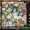
Of course it does not work. It is built on a solderless breadboard. Use a breadboard for little light bulbs or LEDs, little motors and little buzzers.
I made hundreds of my prototypes (some very complicated) with their parts and a few short jumper wires neatly soldered on stripboard. The strips of perforated copper formed half of a pcb and the parts formed the other half. They all worked perfectly and many were sold as the finished product. It was easy to see where connections were made because there was no messy tangle of wires all over the place like on your breadboard and there was no capacitive-coupling causing feedback like between your many wires ands rows of contacts. Also no intermittent contacts.
I now understand that breadboard causes problem but whats the point with a breadboard if not testing things before soldering?
Whats wierd in this case is that I have the "inverted" version soldered on pcb and tested the same diagram on breadboard with same result. Both working. would be more happy if the inverted failed on the bredaboard
An inverting opamp has the input and output with opposite phases so they cancel.
A non-inverting opamp has the input and output with the same phase so just a little bit of capacitance between all the wires or rows of contacts on a breadboard causes it to oscillate.
An inverting opamp has the input and output with opposite phases so they cancel.
A non-inverting opamp has the input and output with the same phase so just a little bit of capacitance between all the wires or rows of contacts on a breadboard causes it to oscillate.
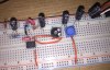
Not At topic, Ideal towards Breadboard issues, The small change effect of the audible output sounds just like the Driver op is acting like a voltage follower on its output. may want to connect the common pin as close as possible to the GND pin and use a capacitor (10-22uF) at the positive pin with the common for the capacitor connected at a primary rail on the bread boards GND, the tracts on the boards often show quite the loss in communication of power flow, even in the same connected row. Also the board I've shown in the attached image has a metal backing with a GND strap to the 5V supply main GND connection.
Solderless Breadboard? Those can be quite annoying to properly ground, The jumper wires often result in current sense effect much like battery chargers use to shut off when batt charged ect. A digital multi tool if avail with some form of self protection built in for a just in case method. Resistance mode auto range or standard low Ohm value. If the circuit is operational in the stable sense (nothing going obviously wrong) and powered on, place the Common test lead to the at most GND point connected to the Breadboard from power supply, then the red test lead at several GND common points only and observe the reading, if well over 4-8 Ohms, that's quite a loss and can cause the components to have a "soft" common resulting in odd behavior. Avoid connecting the red test lead to positive power as applied to the test tool in resistance mode can cause damage to some testers, use caution! this is just an example image of a board using an LinCmos push pull comparator with an LMT84 temperature sensor as the driver and the hassle of wires and multiple common jump points all across the board. Avoiding voltages above 15 Volt for many meters when testing for common losses in resistance mode this way.
Hope this is somewhat helpful (for bread boarding if not all ready known)
Im a beginner when it comes to all of this. This is not things I normally work with or learned from any school. Mot things are new to me but I always learn something new from everything I try to do even if I fail or success. Maybe one day I dont have to stress this forum with all basic questions
Good to hear about multimeter.
Dont be mad now but its a 12v computer psu . No fancy variable desktop psu.
I tested with another LM358 and the "hifi IC", with same result.
Be better to use the desktop power supply.
Unless the circuit is oscillating, there is something we are missing.
After all this is a simple amplifier circuit which has been used by the million.
Can you do this to check if the circuit is oscillating:
(1) Remove all input and output connections
(2) Connect a 470 Ohm resistor to the anode of 1N4148 small signal high speed diode.
(3) Connect the cathode of the diode to a 100nf ceramic capacitor.
(4) Connect the other end of the capacitor to the 0V line (close to the opamp output)
(5) Connect your multimeter set to around 10V across the capacitor
(6) Connect the free end of the resistor to the outputs of the two opamps in turn
If you get a voltage reading on your meter, the opamp is oscillating (or picking up hum).
Thanks spec! Appreciate that you have patience with me
If I understand you correctly.
Should I read 0v across capacitor with the mulitmeter when 47ohm is connected to the output (pin 1) and when the capacitor (100nF) is connected to 0v? (and the diode in between)
That is giving me 0.009v
Looks like this now (whitout the resistor, diode, capacitor-thing)
still no luck with the potentiometer (gain). Tested two pots same with both.
Should I read 0v across capacitor with the mulitmeter when 47ohm is connected to the output (pin 1) and when the capacitor (100nF) is connected to 0v? (and the diode in between)
That is giving me 0.009v
My post was not clear the resistor should have been 470 Ohms.
Otherwise all is correct and the opamps are not oscillating.
Can you try again with 470 Ohms and if the reading on your meter is still essentially zero volts, the opamps are not oscillating.
With the resistor, diode, capacitor and meter connected to one of the opamp outputs, can you then inject a signal into the inputs of the opamp and see if you get a DC reading on the multimeter which varies with the input signal amplitude.
This site uses cookies to help personalise content, tailor your experience and to keep you logged in if you register.
By continuing to use this site, you are consenting to our use of cookies.

")