Continue to Site

Welcome to our site!

Electro Tech is an online community (with over 170,000 members) who enjoy talking about and building electronic circuits, projects and gadgets. To participate you need to register. Registration is free. Click here to register now.

  • Welcome to our site! Electro Tech is an online community (with over 170,000 members) who enjoy talking about and building electronic circuits, projects and gadgets. To participate you need to register. Registration is free. Click here to register now.

adding indicator to show charge complete

Status
Not open for further replies.

aruna1

Member
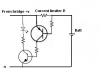
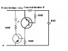
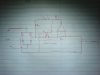
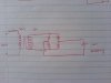
guys I'm using following circuit to charge my 12V 1500mAh NiMH battery.(with 230V --> 15v step down transformer and a rectifier bridge)
is there any way i can put a indicator led or something to indicate charge complete status? (very simple circuit will be great).i was thinking if i put a series LED with battery will it go off once battery is fully charged?
thanks
 

Attachments

  • DSC01982.JPG
    DSC01982.JPG
    739.7 KB · Views: 506
That doesn't look like a charger. You need to control the charging current by using a series resistor wrt the battery specifications and transformer output

Voltage drop across the resistor can be used to switch ON a transistor to indicate the charging process. I think the series LED will do the job at least.

EDIT: Attached a reference figure :)
 

Attachments

  • chge.PNG
    chge.PNG
    13.1 KB · Views: 284
Last edited:
That depends on transformer current ratings.

Suppose, for a 750mA transformer, 750/10R=75mA you'll get as constant charging current if you apply 10R limiter resistor.

So 1500mAh/75mA = 20hrs time for topping up the battery(approx.!)

Refer the new image for rest of the values :p and feel free to experiment of it and let me know :D
 

Attachments

  • chge.PNG
    chge.PNG
    13.8 KB · Views: 250
That depends on transformer current ratings.

Suppose, for a 750mA transformer, 750/10R=75mA you'll get as constant charging current if you apply 10R limiter resistor.

So 1500mAh/75mA = 20hrs time for topping up the battery(approx.!)

Refer the new image for rest of the values :p and feel free to experiment of it and let me know :D
thanks I'll let you know.
one more question
transformer i use is (7.5V-0V-7.5V 300mA) one. i use it as 15 v transformer(by removing center tap) .so is that mean i get 15V 300mA from it?
 
Are you trying to build a bomb? :rolleyes:

NiMH batteries don't like overvoltage! :eek:

15V out of the transformer results in close to 20V when using a bridge rectifier (or four single diodes wired as bridge rectifier) at nominal current. As the battery gets fully charged the current decreases and the voltage rises to the idle voltage of the transformer which is normally 1.3 to 1.4 times the nominal voltage. It means the voltage will increase to 28.3V at zero current.

You'd be better off using a MAX712 to charge the batteries properly. It can be (wire) programmed for 1 to 16 NiMH cells. The MAX712 terminates charging when detecting zero voltage slope.

Boncuk

is there any replacement for max712? max icsare hard to find in loal stores (except max232) and ordering them takes too long
or what if i use zener diode to get fixed voltage output? will that work?
 
Last edited:
another idea

I was thinking will following circuit will work as automatic cutoff system when battery is fully charged?

initially optocoupler is off.we press S1 to turn on optocoupler hence powering up the circuit and begin charging the battery.as long as current flow through output of op amp will be high and optocoupler remains turned on.when battery is fully charged current flow through RL will be zero,therefore voltage difference between inverting input and non-inverting input of op amp becomes zero.this will turn off the optocoupler.and it will also cut power to entire circuit.
 

Attachments

  • DSC01985.JPG
    DSC01985.JPG
    620.1 KB · Views: 375
Hi aruna1,

I'll work out a circuit for you to cut power off when the battery reaches full charging voltage, also indicating charge complete.

Boncuk
 
Hi aruna1,

I'll work out a circuit for you to cut power off when the battery reaches full charging voltage, also indicating charge complete.

Boncuk

thank you boncuk.
what do you think about my above idea?
(i think it need a non inverting amplifier+comparator,not only a comparator,and a smoothing capacitor after the bridge)
thanks
 
Last edited:
Are you trying to build a bomb? :rolleyes:

NiMH batteries don't like overvoltage! :eek:

15V out of the transformer results in close to 20V when using a bridge rectifier (or four single diodes wired as bridge rectifier) at nominal current. As the battery gets fully charged the current decreases and the voltage rises to the idle voltage of the transformer which is normally 1.3 to 1.4 times the nominal voltage. It means the voltage will increase to 28.3V at zero current.

Boncuk

second thought my circuit may not do the job.as you said bridge output voltage may become 28.3v how about if i put a circuit to monitor voltage of battery and cut off charging when it reaches to about 14V?
 
Status
Not open for further replies.

Latest threads

New Articles From Microcontroller Tips

Back
Top