Continue to Site

Welcome to our site!

Electro Tech is an online community (with over 170,000 members) who enjoy talking about and building electronic circuits, projects and gadgets. To participate you need to register. Registration is free. Click here to register now.

  • Welcome to our site! Electro Tech is an online community (with over 170,000 members) who enjoy talking about and building electronic circuits, projects and gadgets. To participate you need to register. Registration is free. Click here to register now.

Fm modulation project

Eliffff

New Member
The term project involves the practical application of frequency modulation (FM) in transmitting images of limited size (typically one LOGO).
Step 1: Text-to-speech conversion (Ardinuio, etc.)
Step 2: Modulate in FM and transmit
Step 3: Receive and Demodulate
Step 4: Filter out and detect.
Step 5: Speech to text conversion
Step 6: Prompt on an LCD screen
How can I design this project ? I understand nothing please suggest books, project like this
Please explain how text and speech is involved in transmitting an image of a logo?
There must be more detail about this project. I can imagine several reasons but not intuitive so I hope there is more detail to get us on the right track.
 
You will convert the image (such as a university logo) into a sound signal using a software program. Then you will convert the sound back into an image with FM receiver and transmitter circuits. You will try to obtain an image similar to the initial image.
 
You will convert the image (such as a university logo) into a sound signal using a software program. Then you will convert the sound back into an image with FM receiver and transmitter circuits. You will try to obtain an image similar to the initial image.
Teacher wants that from us but I dont know where I start can you help me
 
Analog vs Digital modulation over FM requires you to scan the contents of a uncompressed grey scale image file for each row then return with sync pulse like a TV signal. You could also use a binary scale B/W but that would not sound as musical. But instead of direct modulation of B/W on FM , you are suggesting a voice subcarrier like 50 to 5kHz deviation or more with at least 128:1 B/W ratio to act as a voice band signal on say a 100 MHz carrier with 75 kHz or so deviation. There are standards for FM and TV, you can read about, or you can invent your own if you think of better way. But using standard designs for mod/demod and TV sync might be one of many ways to do this.

There are also license free bands called ISM where you can use a carrier and use FM more modulation with the width greater than the spectrum of the signal for improvement on SNR vs CNR . Make a block diagram with I/O specs then fill in the blanks as you learn how to do it. Like XY LOGO rows x columns at 96 dpi (std monitor) then make the maximum signal a narrow pulse for sync then the white level then the 8 bit pixel value D/A as the analog level scaled to 0 to 100% of frequency using a linear FM carrier modulator. And counters for H pixel and Y pixel to sequence the bytes to analog while inserting a sync pulse 0/100% before each line and steady carrier before means no image. You can use AI to search for clues using this example and find a better way.(maybe)
 
Last edited:
You can even do your favorite album cover or an XRAY image or just emoticons. Each image format has different structure. FAX transfers on VHF Tx/Rx cards beween two 56kHz modems but done quite differently yet 56k could easily be FM or AM modulated with modems at both ends, but that is a digital method on mod/dem units might be a bit too complex or too easy if you get permission to do it differently.
 
Last edited:
Tell your Prof a better design assignment has specs for the interface and quality of image so it can be measured. Tell 'em I said so.

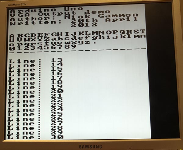
Surplus VGA monitor free
 
Slow Scan television is probably the simplest overall approach.

That allows images to be sent as audio, through eg. Amateur Radio gear - or licence-exempt walkie talky style radios.


Tell your Prof a better design assignment has specs for the interface and quality of image so it can be measured. Tell 'em I said so.

Surplus VGA monitor free
Thank you so so so much thank you for your advice
 
Slow Scan television is probably the simplest overall approach.

That allows images to be sent as audio, through eg. Amateur Radio gear - or licence-exempt walkie talky style radios.


Ohh God boom thank you so so so much this will help me a lot
 
Beware that your steps 1,5,6 are not being followed which are already vague so verify if important.
 
2D images may be in Analog raster or vector format depending on how the image is created. Cameras are raster format but several different colour formats are possible. Monitors started as analog (VGA) and then both VGA & digital (HDMI). Since this project defines the medium format as Analog, you still must be aware of all the possible I/O formats available and which you will accept, process or exclude.

An image captured can be transmitted (Tx'd) in FM and Rx'd without any Arduino or ARM uC ever needed. This would be a simple "black box" solution. For educational purposes, you are tasked to create something more discrete yet undefined for Input/Output (I/O) such as a "Logo" image. Graphic designs such as this are often done in a vector format which can be more efficient in memory when scaling up in size with the same smooth curves.

Although simple in concept, it does not define the format of all possible formats. The design process begins by you expanding the details in your "Design Spec" while ensuring it still satisfies the original intent while you clarify with your "customer" (Prof) as required with questions for "must have" vs "may have". Then you will list which formats you will choose, accept, process and exclude.

Since this project specifies the modulation to be analog FM you must define which image format(s) will be used for input and output. Also commonly used is AM, PM, QPSK.

Monitor LCDs are both analog (VGA) and digital (HDMI). Image capture devices are inherently analog but may convert to digital in a raw raster format, or decimated to a smaller array size, processed and compressed to a smaller image file.

The image could also be created by design in a vector XY format vs a raster pixel map. The analog pixel spec, can be the common raw 8bit*RGB format =24 bits per pixel (24 BPP), 8 BPP, 4 BPP, or 1 BPP (B/W). Higher resolutions are also available for non-standard requirements like XRAY photos.

You must consider all formats and if using a uC what libraries are available for conversion to the transmission format that you choose to receive (Rx)
colour depth, greyscale or B/W. This also affects the format of the analog signals such as simple Fax (B/W) or Colour 24 Bit. or anything in between.

There are no right or wrong choices if it still meets all your "customer's" requirements then it is perfect. Some may want to exceed "Must Have " specs with "May Have" features if it does not add significant cost or effort for bonus points. The choices are all yours.

If your "Design Spec" also includes measurable specs for design such as signal levels and signal/noise ratio, resolution, sharpness, echo-free, and jitter-free then you can also include Design For Testability specs (DFT) with test points (TP) identified. Standard test patterns may be specified for conformity and tolerance.

Not mentioned but assumed are the environmental specs, which could be defined as "Benign" ground fixed, limited room temperature range. Any stress such as temperature or supply can affect the tolerances of analog parameters, which must be met.

Often "customer specs" are unspecified, vague or implementation restricted for good or bad reasons. While creating your "Design Spec" confirm each requirement as you question the tolerances or suggest alternatives. This will help you focus the big picture ( no pun intended) and break it down into smaller boxes in your "block diagram" each with I/O specs in your design specs. Once understood finding/ creating /choosing the best solutions becomes easier.

Keep in mind, there may be unspecified "customer specs" for presentation, cost and timeliness as well as conformance to specs.
 
Last edited:
Modulation, classic is to alter an oscillators frequency by some method.

In "typical" FM that is RF, and oscillator freg determined by LC circuit with a
transistor. Freq is ~

1716025020998.png


So we can change L or C with a modulation scheme. Since modulation rate is
typically high changing L is typically impractical, so we change C. How do we do that ?
A very common method is to use a reverse biased diode where its C is proportional to
its Vreverse.


Regards, Dana.
 
2D images may be in Analog raster or vector format depending on how the image is created. Cameras are raster format but several different colour formats are possible. Monitors started as analog (VGA) and then both VGA & digital (HDMI). Since this project defines the medium format as Analog, you still must be aware of all the possible I/O formats available and which you will accept, process or exclude.

An image captured can be transmitted (Tx'd) in FM and Rx'd without any Arduino or ARM uC ever needed. This would be a simple "black box" solution. For educational purposes, you are tasked to create something more discrete yet undefined for Input/Output (I/O) such as a "Logo" image. Graphic designs such as this are often done in a vector format which can be more efficient in memory when scaling up in size with the same smooth curves.

Although simple in concept, it does not define the format of all possible formats. The design process begins by you expanding the details in your "Design Spec" while ensuring it still satisfies the original intent while you clarify with your "customer" (Prof) as required with questions for "must have" vs "may have". Then you will list which formats you will choose, accept, process and exclude.

Since this project specifies the modulation to be analog FM you must define which image format(s) will be used for input and output. Also commonly used is AM, PM, QPSK.

Monitor LCDs are both analog (VGA) and digital (HDMI). Image capture devices are inherently analog but may convert to digital in a raw raster format, or decimated to a smaller array size, processed and compressed to a smaller image file.

The image could also be created by design in a vector XY format vs a raster pixel map. The analog pixel spec, can be the common raw 8bit*RGB format =24 bits per pixel (24 BPP), 8 BPP, 4 BPP, or 1 BPP (B/W). Higher resolutions are also available for non-standard requirements like XRAY photos.

You must consider all formats and if using a uC what libraries are available for conversion to the transmission format that you choose to receive (Rx)
colour depth, greyscale or B/W. This also affects the format of the analog signals such as simple Fax (B/W) or Colour 24 Bit. or anything in between.

There are no right or wrong choices if it still meets all your "customer's" requirements then it is perfect. Some may want to exceed "Must Have " specs with "May Have" features if it does not add significant cost or effort for bonus points. The choices are all yours.

If your "Design Spec" also includes measurable specs for design such as signal levels and signal/noise ratio, resolution, sharpness, echo-free, and jitter-free then you can also include Design For Testability specs (DFT) with test points (TP) identified. Standard test patterns may be specified for conformity and tolerance.

Not mentioned but assumed are the environmental specs, which could be defined as "Benign" ground fixed, limited room temperature range. Any stress such as temperature or supply can affect the tolerances of analog parameters, which must be met.

Often "customer specs" are unspecified, vague or implementation restricted for good or bad reasons. While creating your "Design Spec" confirm each requirement as you question the tolerances or suggest alternatives. This will help you focus the big picture ( no pun intended) and break it down into smaller boxes in your "block diagram" each with I/O specs in your design specs. Once understood finding/ creating /choosing the best solutions becomes easier.

Keep in mind, there may be unspecified "customer specs" for presentation, cost and timeliness as well as conformance to specs.
actually prof wants a basic project guess I will make this at arduino I research basic sstv radio I will try to make at arduino
 
actually prof wants a basic project guess I will make this at arduino I research basic sstv radio I will try to make at arduino
Even simpler projects need a design spec and good planning. The too simple solution is to buy the boards with code, then you learn very little. It might not even use FM and be painfully slow or just 1bit resolution. I suggest you compare what others use and what Prof expects.

It may surprise you to know that nice free software for MMSSTV works on Win7 and interfaces to a bunch of SDR radios with serial ports that are worth at least a couple thousand dollars each. Otherwise the primitive ones are 1 bit resolution and painfully slow. So follow my suggestion and determine your budget and time limit with how much you are willing to learn with careful exploring options and planning then choose one & create a design spec and simple test plan before wasting too much time or money. ... or not at your own peril.

Besides this is Analog telemetry design right?
 
Last edited:
Even simpler projects need a design spec and good planning. The too simple solution is to buy the boards with code, then you learn very little. It might not even use FM and be painfully slow or just 1bit resolution. I suggest you compare what others use and what Prof expects.

It may surprise you to know that nice free software for MMSSTV works on Win7 and interfaces to a bunch of SDR radios with serial ports that are worth at least a couple thousand dollars each. Otherwise the primitive ones are 1 bit resolution and painfully slow. So follow my suggestion and determine your budget and time limit with how much you are willing to learn with careful exploring options and planning then choose one & create a design spec and simple test plan before wasting too much time or money. ... or not at your own peril.

Besides this is Analog telemetry design right?
Yes it is. I dont have much time I have fm modulation and demodulation circuits they works and I will use them at mmsstv
 
Even simpler projects need a design spec and good planning. The too simple solution is to buy the boards with code, then you learn very little. It might not even use FM and be painfully slow or just 1bit resolution. I suggest you compare what others use and what Prof expects.

It may surprise you to know that nice free software for MMSSTV works on Win7 and interfaces to a bunch of SDR radios with serial ports that are worth at least a couple thousand dollars each. Otherwise the primitive ones are 1 bit resolution and painfully slow. So follow my suggestion and determine your budget and time limit with how much you are willing to learn with careful exploring options and planning then choose one & create a design spec and simple test plan before wasting too much time or money. ... or not at your own peril.

Besides this is Analog telemetry design right?
Additionally, I used a matlab code to convert the logo into an audio signal, and then I want to convert it back to visual with FM transceiver circuits. I have fm transceiver that work but I cannot make this yet.Is it possible to set up this project in digital environment?
 
Strictly speaking, the audio is an "FM" version of the scanned image, without ever using a radio link!

The information is sent as a varying frequency signal - though in the audio spectrum.
 

Latest threads

New Articles From Microcontroller Tips

Back
Top