mading2018
Member
I figure out that this could be done as well,.
--edit--
alec_t, do you think it is okay if I skip to use GTDR? It is to complicated to implement with the circuit. I have no idea how to do it. I mean, the solution that I have right now, it is "good enough" to be an totem-pole?
--edit--
alec_t, do you think it is okay if I skip to use GTDR? It is to complicated to implement with the circuit. I have no idea how to do it. I mean, the solution that I have right now, it is "good enough" to be an totem-pole?
Attachments
Last edited:
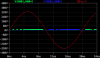
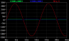
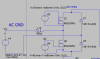
") , so now it works. Do you think this is okay, I know that Q1 and Q2 is not constant, I mean maybe it close enough to operating as a totem-pole?
, so now it works. Do you think this is okay, I know that Q1 and Q2 is not constant, I mean maybe it close enough to operating as a totem-pole?