Continue to Site

Welcome to our site!

Electro Tech is an online community (with over 170,000 members) who enjoy talking about and building electronic circuits, projects and gadgets. To participate you need to register. Registration is free. Click here to register now.

  • Welcome to our site! Electro Tech is an online community (with over 170,000 members) who enjoy talking about and building electronic circuits, projects and gadgets. To participate you need to register. Registration is free. Click here to register now.

555 timer problem

Status
Not open for further replies.

Worlddisgrace

New Member
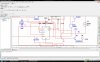
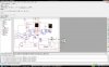
my 555timer output seems to have been red and bitten, but the circuit is able to run in NI Multisim ,

Please tell me why is my 555 timer output red.. if u know


THANKS:DDD
 
Last edited:
Read .
 
Look at the picture i attached , at the 555 timer output, it turns out to be red ><!

Any idea why?
 

Attachments

  • PROBLEM.jpg
    PROBLEM.jpg
    246.7 KB · Views: 328
U9A, and perhaps many other locations, is in wiring conflict with pin 3 of the 555. Both are positive outputs, and many sims won't put up with that. Check the help section of yours for a definition.
 
Why do the schematics have so many wires crossing and uncrossing, going up down left and right, zigging and zagging and basically going all over the place? Each wire should be a straight line.
There is one wire that completely circles the 555. Why?
 
Someone doesn't know how to use bus or port wires =\
 
The output of the 555 is blowen, kaput
perhaps post the multisim file.
looking at the schematic and being a nerwbi with multisim trying to figure out what X6 is. looks like an LED?
what is this circuit supposed to do? a two digit counter?
 
Why do the schematics have so many wires crossing and uncrossing, going up down left and right, zigging and zagging and basically going all over the place? Each wire should be a straight line.
There is one wire that completely circles the 555. Why?

multisim likes to make a path on it's own, regardless of what the user wants. the problem is that when a part is moved all of the connections change their positions as well. it's not the best system in the world (especial when a simulation error occurs) but it can get the job done.
 
The output of the 555 is blowen, kaput
perhaps post the multisim file.
looking at the schematic and being a nerwbi with multisim trying to figure out what X6 is. looks like an LED?
what is this circuit supposed to do? a two digit counter?

X6 is a lamp probe
 
Thanks all for the reply.
It really helps.
I am a freshman in electronics.
This circuit is actually a counter, that will count up to 5 and then down to 0 , but i want to set a monostable 555timer for a time delay at 5. meaning 1-2-3-4-5 (stops for 3sec) then count down .

Anyone can help me with the 555 mono, i look at many online schemetics, tried and failed many times, but i'll keep trying.

Thanks all for your reply.
 
i think i know what your problem is, you have the output of an AND gate feeding into the output of your 555 timer, if i'm not mistaken then the 555 is not capable of sinking that much current. add a diode to the output of the 555 and the AND, so that they still trigger a clock pulse. Also, if you are a newbie to electronics, then how were you able to make this circuit?
 
Thanks all for the reply.
It really helps.
I am a freshman in electronics.
This circuit is actually a counter, that will count up to 5 and then down to 0 , but i want to set a monostable 555timer for a time delay at 5. meaning 1-2-3-4-5 (stops for 3sec) then count down .

Anyone can help me with the 555 mono, i look at many online schemetics, tried and failed many times, but i'll keep trying.

Thanks all for your reply.

multisim usualy has a "circuit builder" under the Tools tab, in there their is a 555 timer wizard that can construct monostable and astable 555 circuits.
 
Status
Not open for further replies.

Latest threads

Back
Top