throbscottle
Well-Known Member
I started looking at ways to limit the inrush current of a motor. It needs to be turned on and off at intervals of several seconds, so a NTC inrush limiter isn't an option since it doesn't cool down quick enough.
The motor will be driven by a IR2153 self-oscillating half-bridge, with simple current based feedback (As per this video:
schematic at 3.00). It's turned on and off via its timing capacitor pin, which can also be pulled down to increase the ratio (like the "cont" pin on a 555) AFAICT.
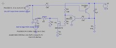
I decided to try a timer based inrush limiter so it doesn't interfere with anything - see schematic - it's just a resistor and capacitor. I've done it so the capacitor gets discharged when the run cycle ends. So at startup the motor's 0v connection goes via the 8 ohm resistor for about 200mS (likely longer in real life), then the mosfet connects it to the 0.1 ohm current sensing resistor. The motor is represented by the 3 ohm resistor, R3. Yes I know a motor is nothing like a resistor but I don't know how to model one.
Simulation works reasonably well - I'm looking for pointers to make it better, eg sharper response, better arrangement of the high current parts, maybe less components. Will having the extra transistor in the circuit interfere with the half-bridge at all?
The motor draws up to 5A no load at 24V (DC not PWM) and something over 10A at startup.
Also, would it be worth using a relay instead of the mosfet?
The motor will be driven by a IR2153 self-oscillating half-bridge, with simple current based feedback (As per this video:
I decided to try a timer based inrush limiter so it doesn't interfere with anything - see schematic - it's just a resistor and capacitor. I've done it so the capacitor gets discharged when the run cycle ends. So at startup the motor's 0v connection goes via the 8 ohm resistor for about 200mS (likely longer in real life), then the mosfet connects it to the 0.1 ohm current sensing resistor. The motor is represented by the 3 ohm resistor, R3. Yes I know a motor is nothing like a resistor but I don't know how to model one.
Simulation works reasonably well - I'm looking for pointers to make it better, eg sharper response, better arrangement of the high current parts, maybe less components. Will having the extra transistor in the circuit interfere with the half-bridge at all?
The motor draws up to 5A no load at 24V (DC not PWM) and something over 10A at startup.
Also, would it be worth using a relay instead of the mosfet?