Continue to Site

Welcome to our site!

Electro Tech is an online community (with over 170,000 members) who enjoy talking about and building electronic circuits, projects and gadgets. To participate you need to register. Registration is free. Click here to register now.

  • Welcome to our site! Electro Tech is an online community (with over 170,000 members) who enjoy talking about and building electronic circuits, projects and gadgets. To participate you need to register. Registration is free. Click here to register now.

555 timer false triggers

Status
Not open for further replies.

thecritic

Member
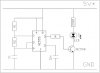
I have a typical 555 timer monostable circuit soldered into a PCB board. A relay is run by the output of the IC (pin 3) after amplifying through a transistor SL100.
IC is set to be triggered by an external push switch.
The problem is that--> sometimes when I use The relay (to pass some Currents through it) the monostable IC is triggered (false). It is also sometimes triggered when a tube light nearby is switched on/off.
It don't always happed, but then also, this circuit has become useless to me, since I need it to be highly reliable.
Where am I getting wrong.

(the circuit I am using is highly popular monostable mode with a push button form ground to pin 2 ; output pin 3 is connected to the base of SL100 transistor which drives the relay)
 
You should have a resistor between the output of the 555 and the transistor base to limit the current.

The relay will be pulling a bit of current and putting noise on the supply. You will need a capacitor across the power supply; try 220u for a start.

You can also try a resistor pullup on pin 2, and maybe a small capacitor also.
 
Hopefully, you are using a diode across your relay coil to snuff out ringing, and capacitors on your power connections to your timer. Since you're getting triggers from external circuits, you might need to shield your circuit form externam EM, and isolate the trigger pin from the rest of the circuit. A suitable value resistor connected in series with the trigger pin might do the trick, and perhaps a small capacitor connected between the pin and ground to pass transients. Also, there is usually a capacitor connected between unsued pins on the timer and ground. I don't remember right now which pins normally requre this, but you can easily find this information using the web.

Good luck.
 
I put this .xls file together a couple of days ago (see attached). It might help you out. It's a simple flasher circuit using a 555 Timer. There's a formula for working out pulse/duty etc in the spreadsheet cells. you can change the cap/resistor values to get the right frequency. This one just drives an LED. Take out the LED and put your relay coil there. You might need some bypass/filtering caps and diode as dougy83 suggested though. -Tom
 

Attachments

  • Calc_555Timer_SQUARE_WAVE_GEN.zip
    17.2 KB · Views: 339
Ignore that, my circuit is astable! do a google image search, the monostable circuit looks very similar to it.

Cheers -tom
 
I can't simply see it since you Zipped it.
My WinZip says it has errors so I can't unzip it anyway.
Please post a PNG file type.
 
it's an excel file with an image in the spread sheet. couldn't attach it so i had to zip it first. I can unzip it at this end. see attached image from the xls file. it should be ignored anyway. as i mentioned earlier, it's not really applicable since mine is an astable circuit, not a monostable circuit. apologies for the confusion. -Tom
 

Attachments

  • img1.JPG
    img1.JPG
    37.4 KB · Views: 638
Hi thecritic,

here is circuit using a non-retriggerable input. It accepts a new input only after the circuit has timed out.

Please note the decoupling cap of 100nF close to the NE555 supply pin and a 220µF electrolytic cap in the supply. If possible place it also as close as possible to the timer IC's supply pins.

Make sure to use a free wheeling diode for the relay. If the relay has to switch a high current load it will also cause false triggering by the spark caused on the relay contactors.

The 1µF coupling cap at the trigger input takes care not to react on false triggering.

Boncuk
 

Attachments

  • NON-RETRIGGERABLE.gif
    NON-RETRIGGERABLE.gif
    11.3 KB · Views: 630
  • NON-RETRIGGERABLE-1.gif
    NON-RETRIGGERABLE-1.gif
    11.2 KB · Views: 962
it's an excel file with an image in the spread sheet.
It is a simple 555 oscillator driving a transistor that blinks an LED at only 9mA. The transistor can be removed because the 555 can drive the LED and its current-limiting resistor easily by itself.
 
Hi thecritic,

here is circuit using a non-retriggerable input. It accepts a new input only after the circuit has timed out.

Please note the decoupling cap of 100nF close to the NE555 supply pin and a 220µF electrolytic cap in the supply. If possible place it also as close as possible to the timer IC's supply pins.

Make sure to use a free wheeling diode for the relay. If the relay has to switch a high current load it will also cause false triggering by the spark caused on the relay contactors.

The 1µF coupling cap at the trigger input takes care not to react on false triggering.

Boncuk
I am getting false triggers not when the relay is switched ON, but when every thing are passive and the circuit is waiting for trigger and then I use the relay's NC (normally closed) terminals to pass some current.
Anyway, I am going to try your suggestions soon. Thanks for that.
 
OK, so I have the diode in across the LM317, it doesn't solve the man. switch issue but more power is going to the motor.
 
The manual switch is still affecting the trigger. Perhaps if I put a diode in between the 555 timer pin 4 and the pump motor, this should isolate the motor from the timer. Of course there is an additional 1.7 V drop from the diode that will reduce the voltage at the pump from 6V to 4.3 V. To keep my 6V at the pump i could increase Vout of the LM317 to 7.7V.
 
The manual switch is still affecting the trigger. Perhaps if I put a diode in between the 555 timer pin 4 and the pump motor, this should isolate the motor from the timer. Of course there is an additional 1.7 V drop from the diode that will reduce the voltage at the pump from 6V to 4.3 V. To keep my 6V at the pump i could increase Vout of the LM317 to 7.7V.
No, that makes no sense I won't get a voltage drop but a current drop. It's kindof amazing that this simple circuit has such issues, everywhere I go on the net this type of circuit in a much simpler form is supposed to work with no issues, I guess it's the difference between the real world and the theoretical world.
 
Status
Not open for further replies.

Latest threads

New Articles From Microcontroller Tips

Back
Top