Electro Tech is an online community (with over 170,000 members) who enjoy talking about and building electronic circuits, projects and gadgets. To participate you need to register. Registration is free. Click here to register now.
Welcome to our site! Electro Tech is an online community (with over 170,000 members) who enjoy talking about and building electronic circuits, projects and gadgets. To participate you need to register. Registration is free. Click here to register now.
So I attempted adding a resistor in series with the timing cap (ground >> timing cap >> resistor >> Disc Pin) and I tried a 100, 470, 1k and 2.2k ohm resistors. I noticed the discharge of the timing cap got faster however still not instantaneous. Any higher value of a resistor did not make any difference. Any thoughts?
Thank you for all your help and the time you’ve put into helping me. I just want to reiterate my circuit fully to you just for a chance that you may have 1 last thought as to why the discharge maybe slow.
The power supply provides 9V to the device, from a test point on the device the timer gets 5V and turns on. The output of the timer is connected to an op amp set up as unity gain to act as a buffer and the output of the op amp goes into the solid state relay. would having a buffer or maybe a wrong selection of a solid state relay play any factor into the discharge being slow? I ask this because as I mentioned earlier the timer on its own does not have a slow discharge issue. It’s only when all of this is connected to each other that this slow discharge becomes a problem.
Yeah, so they are 2 different things. I am not sure if I can share a full schematic of the device. But let me put it this way.
the purpose of this project, for the lack of a better word, is to have a timer that will automatically shut off the device if the person using it forgets to turn it off when they’re done using it. However, the timing should be able to reset if the device is in use.
The first picture is a Block diagram of the whole system excluding the schematic of the device (which I don’t believe plays a roll exactly in what I’m trying to do.) another thing missing from this schematic is the op amp, which the output of the timer connects to. The output of the op amp then goes to “pin 3” of the SSR.
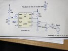
The second picture is the schematic of the timer circuit itself.
I'm unclear about your setup, but it seems to me that the power to the 555 timer gets switched off at the same time as the mystery device. If so, the discharge transistor inside the 555 won't be conducting so the timing cap won't discharge quickly.
This site uses cookies to help personalise content, tailor your experience and to keep you logged in if you register.
By continuing to use this site, you are consenting to our use of cookies.