Continue to Site

Welcome to our site!

Electro Tech is an online community (with over 170,000 members) who enjoy talking about and building electronic circuits, projects and gadgets. To participate you need to register. Registration is free. Click here to register now.

  • Welcome to our site! Electro Tech is an online community (with over 170,000 members) who enjoy talking about and building electronic circuits, projects and gadgets. To participate you need to register. Registration is free. Click here to register now.

555 Timer Circuit

Status
Not open for further replies.

hhaibert7

New Member
Hello,

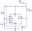
I am using a 555 timer circuit in a monostable mode. Its output is going to a relay through a buffer and the relay is connected to another circuit. The over all project is to turn on a device and have the device be on for a predetermined time UNLESS activity is detected. If a user uses the device, the device gets a 60kHz signal which gets converted to a short pulse. This pulse then is supposed to be used to reset the predetermined time of the 555 to start the time over. I have successfully integrated the 555 timer in this device so that it turns on and turns off in about 2 minutes (chose this time for test purpose) however where I am having an issue is using the signal to reset the time. I have attached a picture of my current 555 configuration. Please help me figure out how to: either set up an external circuit to help with the time reset or if you have better suggestions on a different timer.
Thank you for your time.

Parts Used:
NE555P timer
UA741 OpAMP (buffer connected to the output of 555)
C2 value 100uF (for a 2 minute time)
 

Attachments

  • 555-timer.png
    555-timer.png
    101.9 KB · Views: 269
This pulse then is supposed to be used to reset the predetermined time of the 555 to start the time over.
Your requirements are not completely clear.
Define "start the time over"?
If the 555 output is high when the reset occurs, what do you want to happen?
Does it just extend the pulse time?
If so, then Pommie's solution should work, using a transistor to momentarily short the capacitor to ground.

LTspice simulation of example circuit below:
Note how the Reset pulses extend the 555 pulse width.

1637123329503.png
 
Last edited:
If a user uses the device, the device gets a 60kHz signal which gets converted to a short pulse. This pulse then is supposed to be used to reset the predetermined time of the 555 to start the time over.

What you've described is a "restartable" monostable 555 timer. If you connect the reset pin to the trigger pin, the timer will reset and restart whenever a trigger pulse is received. See below.

The waveform window below shows the restart pulse causing the timer to reset and restart the timing cycle.
After the third pulse no further pulses occur so the timer completes the 120 second timing cycle.

1637133054194.png
 
The problem with connecting the reset pin to the trigger pin is that while the input is low, the output is also low. The OP appears to want it to stay high. Or, that's how I interpreted it. Only the OP can clarify.

Mike
 
Agree with Pommie. The problem from day 1 (in 1972 - !) is that the 555 is neither

a) a true monostable (positive feedback makes the output pulse width completely independent of trigger pulse timing);

nor

b) a true retriggerable monostable (trigger pulse during the timing cycle restarts the cycle without bouncing the output).

The innergoogle is full of workarounds for various specific operational conditions, and Wally's circuit in post #3 should work here.

Another approach is to change to a CD4060 counter. Multi-minute timing does not require a relatively large electrolytic capacitor, and resetting in instantaneous without a large discharge current spike. A tradeoff is that you lose the 555's beefy output stage, but the TS already is using an outboard relay driver.

ak
 
Hmmm…not the way I interpret the Ops request. The Op very clearly states for the “time to start over”.

I guess we’ll see.
 
UA741 OpAMP (buffer connected to the output of 555)
Why use an op-amp with an output current limit of 20mA to drive the relay when the 555 (if it's the bipolar version) can source/sink around 200mA ?
 
What accuracy are you seeking for your timing ? Do you care about power up transient behavior ?
T and V effects as well, is that of concern, their effects on timing...?


Regards, Dana.
 
Your requirements are not completely clear.
Define "start the time over"?
If the 555 output is high when the reset occurs, what do you want to happen?
Does it just extend the pulse time?
If so, then Pommie's solution should work, using a transistor to momentarily short the capacitor to ground.

LTspice simulation of example circuit below:
Note how the Reset pulses extend the 555 pulse width.

View attachment 134484
by time start over I am referring to this possible scenario:
user turns device on, the timer is preset to 2 minutes.. it has been 1 minute and now the device has sensed activity. the time has been reset back to 2 minutes and the count down starts all over
 
Why use an op-amp with an output current limit of 20mA to drive the relay when the 555 (if it's the bipolar version) can source/sink around 200mA ?
The reason for using the opamp is because I was experiencing an impedance mismatch. the relay was loading down the timer.
 
I apologize for the confusion due to my failure to explain more detailed.
The purpose of this project is to integrate a timer with an already existing device. The device is used as a tester. when the device is used and the test it is completing is successful, a 60kHz signal is detected and a green light turns on. My timer circuit is supposed to be used to modify and make this device more efficient by eliminating the error of "the user forgot to turn the device off and now the battery is dead." in other words, the timer is to be turned on when the device is turned on and after a set time of no activity (i.e. 2 minutes) turn off. However, if the device has been on for 1 minute, then the 60kHz signal is detected the timer should reset back to 2 minutes instead of turning off in the remaining 1 minute.
Hope this makes sense.

Thank you for all the replys. I am attempting to go through them all while analyzing the circuits and suggestions provided.

Thank you all for your time.
 
The reason for using the opamp is because I was experiencing an impedance mismatch. the relay was loading down the timer.
Impedance matching is rarely a good idea, and certainly not in this case. The 555 is designed to feed a relay (and does so perfectly), a 741 isn't designed to feed a relay and is unlikely to do so for most relays.

Why did you imagine an impedance mis-match?, and whydid you think it might be a problem?..
 
if the device has been on for 1 minute, then the 60kHz signal is detected the timer should reset back to 2 minutes instead of turning off in the remaining 1 minute.
Assuming you want the output to stay on after the reset, then I think the circuit I show in post #3 will do what you want.
 
Impedance matching is rarely a good idea, and certainly not in this case. The 555 is designed to feed a relay (and does so perfectly), a 741 isn't designed to feed a relay and is unlikely to do so for most relays.

Why did you imagine an impedance mis-match?, and whydid you think it might be a problem?..
The output of the timer was dropping significantly when connected to the timer. (input of the timer is 5V and output was 1.5 which was not working with the relay. When I added the buffer this issue was resolved. now what your suggesting may have to do with what relay I am using? since I do not have too much knowledge on relays yet I had a DC60MP relay and so maybe I am using a wrong relay for this application.
 
Assuming you want the output to stay on after the reset, then I think the circuit I show in post #3 will do what you want.
Thank you for your response. your assumption is correct: I do want the output to stay on after the reset. I will be experimenting with that circuit you have provided to see how it would work out. I do want to clarify with you one thing, the source you are using in the lower right hand corner with the label reset, what source is that? I am assuming that is not my V+ 5V source, correct?
 
Using Pommie's and Crutschow's ideas, if the temporary shorting of the timing cap results in relay drop-out then a diode and cap could be added to prevent that.
The circuit below shows the principle (Rt and Ct would need to be increased for your particular time period. C3 would need selection to suit the relay coil characteristics) :-
Retrig555.jpg


Va, Vb and Dx are for the simulation only.
 

Attachments

  • Retrig555.asc
    3.1 KB · Views: 225
I do want to clarify with you one thing, the source you are using in the lower right hand corner with the label reset, what source is that? I am assuming that is not my V+ 5V source, correct?
That is where the signal from the 60 kHz detector comes in to restart the timing period. We don't know what the signal is (switch contact closure, relay contacts, open-collector output, TTL or CMOS logic output, etc.) or its logic polarity, so he put in a generic connection point.

ak
 
The output of the timer was dropping significantly when connected to the timer. (input of the timer is 5V and output was 1.5 which was not working with the relay. When I added the buffer this issue was resolved. now what your suggesting may have to do with what relay I am using? since I do not have too much knowledge on relays yet I had a DC60MP relay and so maybe I am using a wrong relay for this application.
Assuming you had everything connected correctly, then the 555 will provide MUCH more drive for a relay - I can only presume you had it connected wrongly?.

However, now you've mentioned DC60MP, that isn't a relay, it's an SSR so requires far less currenr than a relay anyway, so even more indication it was connected wrongly.
Nigel: Thank you for your response. Attached below is the schematic of how I connected the timer to the SSR (by relay that is what I was referring to, my apologies for the use of wrong terminology). As you can see the switch is connected to the SSR's terminals 1 and 2 and to the battery. The switch turns the device on via the red arrow. the timer then receives its 5V from the device and is powered on. the output of the timer goes to the SSR's control 3. (you can ignore SW2)
Capture.PNG
 
Status
Not open for further replies.

Latest threads

New Articles From Microcontroller Tips

Back
Top