Continue to Site

Welcome to our site!

Electro Tech is an online community (with over 170,000 members) who enjoy talking about and building electronic circuits, projects and gadgets. To participate you need to register. Registration is free. Click here to register now.

  • Welcome to our site! Electro Tech is an online community (with over 170,000 members) who enjoy talking about and building electronic circuits, projects and gadgets. To participate you need to register. Registration is free. Click here to register now.

250W KRK 10s Active Sub Monitor Unable to Power On despite Intact Fuses

Status
Not open for further replies.

solaraxis

Member
I'm a music maker and freshly budding circuit board enthusiast. I'm also extremely exhausted as I'm writing this so forgive the the short bits of info and any other thing that'll come off as lazy. I'll refine this and gloss over every detail to my current knowledge about my issue better when im rested. But here are the details. I really need help and I can't find any forums or documents online addressing this. I get zero power. No light, no hum, it's dead. The fuses below the power in box on the back seemed fine, and I double checked swapping voer another pair of fuses rated the same voltage but 1 amp higher. Still nothing. Absolute silence. I'm heart broken I really need to be able to monitor low end frequencies and without it it's impossible. Heres what I think may have happened...

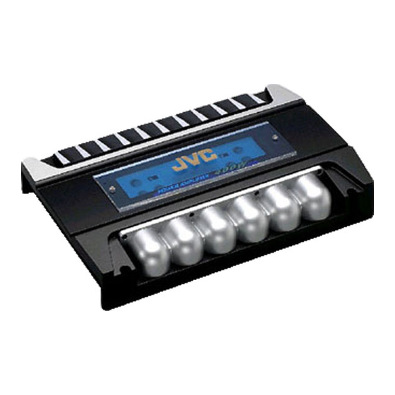
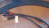
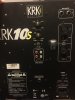
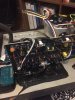
I was experimenting with 5.1 digital surround, however I was lacking a pair of rear speakers. Now the way the 10s works is it acts as a passthrough for the signal that goes to your stereo monitors, applying a filter cut you can adjust to make sure everything is putting out the right tones. I think its safe to assume it also takes the stereo signal it recieves, processes it as mono then sends it back out as stereo, among its other features.. Needless to say, I wasnt going to get 5.1 surround with only three audio outputs and 4 speakers so like any rational person I isolated the signal and sent dobly 5.1 sub channel to the 10s, the left and right rokit 5 monitors were now independent on their respective channels also pushing a quieter more spacious rear left and right signal to emulate the rear positioning. After hours and hours of experimenting I finally managed to get it sounding pretty good, didnt blow any breakers, no other tech suffered damage, I was in the clear. I was compensating my patch cords a bit at this point and ended up using one of these https://www.amazon.com/RapcoHorizon-YSFM-XLR-Insert-Cable/dp/B0007VXZXQ. I think most things default to left for mono so i just sent the left channel in, and sitting right next to the amps left input is an output , and a vacant jack. I figured since I came this far, I might as well see what happens so I dropped the gains, inserted the cable and listened/looked for interference of any kind, at which point I heard none, just nice clean sub frequencies in surround. I watched the terminator 2 like that, listened to some music, played some video games, enjoying the fruits of my labor.

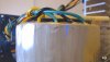
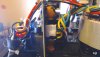
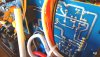
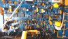
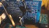
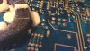
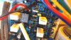
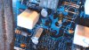
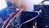
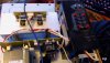
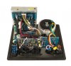
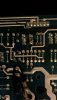
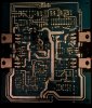
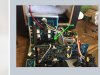
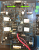
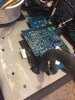
I don't know exactly when it happened, i think it was that night. I vaguely remember unplugging the output as well but i really cant be sure. Im trying to finish a project in the next few months but theres no way i could possibly do a proper mix now. I looked at the guts behind the backplate and with my dull-2-circuitboard eyes tried to see if i short circuited anything but I couldn't see any burns and breaks.. My best guess is that I sent a reversed oscilating electrical signal through that alternator looking coil and toasted it. the board itself looks really good to my knowledge..

Please if there is an expert who reads this, give me some direction. And I'm sorry if my lack of technical electrical knowledge is lacking and I sound dumb. Please help.
 
It looked from the question like you were going to post further information.

Have you tried a different power cable & a different wall outlet? That's the first test, to be sure power is actually reaching the speaker.

If it's still not working, post pictures of the internals of the speaker - both sides of the circuit board and the inside and outside of the back panel, if possible?
 
(rjenkinsgb posted while I was writing this)

Most of the contributors to this forum aren't interested in the story. We're only looking at the details.

Have you got any information other than in the title? I've looked up a 150W KRK 10s Active Sub Monitor on Google, and there's a photo of the back on Amazon, and it looks as though it contains a toroidal transformer. I would expect some sound as you connect that up.

As rjenkinsgb said, we need more to work on. Do you have a multimeter to make basic checks?
 
My apologies, I forgot how I worded my initial post and was unsure if this had even reached anybody. Here are the details..

interface was a saffire pro 24 being powered from the computers firewire connection

all active speakers present Rokit 5 KRK G3, KRK 10s, Edison 2000 powered off the same power bar

The last time it was working, I plugged the 1/4" of this cable (see picture) into the output of my audio interface which sent a mono sub frequency audio signal into the XLR input of the left channel of the 10s sub monitor. I then plugged the other XLR avalable on the Y cable into the XLR output of the left channel (-sending little to no audio signal back to the interface as it would have been processed through the built in lowpass filter cutoff present to send only the frequencies the sub speaker is not playing.) I believe this caused an electrical feedback loop. I have attempted multiple AC power cables and clarified that the AC output on the wall were working. I've also replaced the fuses.
During the time this loop was present there were zero signs that there was a disruption or interference of any sort, no audible feedback, no smell of smoke or burning, no other electrical failures. there is a possibility that a 48v phantompower current was present to power a passive microphone but I don't think that current makes it to the outputs of the interface. If I can recall correctly, it stayed plugged in this way up until it stopped making sound, to which I noticed there was no LED light indicating it was on. Flipping the power switch did nothing. I did not touch the 120v-240v switch. It has been dead from this moment on.
I opened the back panel revealing the boards and examined it thoroughly for signs of failure with no success. I have an electrical friend coming over later this week with a multimeter.
 

Attachments

  • 2020-01-26_14-45-30.jpg
    2020-01-26_14-45-30.jpg
    63 KB · Views: 287
  • subbb.jpg
    subbb.jpg
    53.1 KB · Views: 302
And here are some good pics of the board. I had to rip these from another thread here on this website another guy started. I read most of that thread, a lot went over my head but it did not seem to be the same problem.


Attachments

  • krrkkbb.jpg
    krrkkbb.jpg
    98.9 KB · Views: 342
  • kkrrkbak.jpg
    kkrrkbak.jpg
    55.4 KB · Views: 287
  • krkbak.jpg
    krkbak.jpg
    165.2 KB · Views: 329
  • kkkrrkk.jpg
    kkkrrkk.jpg
    738.7 KB · Views: 506
  • krrkk.png
    krrkk.png
    1.7 MB · Views: 303
  • kttk.jpg
    kttk.jpg
    3.7 KB · Views: 294
  • krrk.jpg
    krrk.jpg
    1.3 MB · Views: 474
  • krk.jpg
    krk.jpg
    4 KB · Views: 311
It could well have been subaudible/inaudible feedback, from what you describe.
Or just pure chance..

We really need photos of the PCB from your unit to look for possible burned components, though it is possible for things to fail with no visible signs.,
The fact that you are not getting a power light hopefully means it's a fault in the PSU rather than amplifier.


I've found the schematics for it on another site: https://music-electronics-forum.com/attachment.php?attachmentid=37246&d=1452554056
[From this site / thread: https://music-electronics-forum.com/showthread.php?t=41162 ]

It looks to be a very straightforward power supply, with everything on its own PCB, separate from the amp etc.
It should be easy to check the outputs from that with just a multimeter.

Edit:
ps. According to some posts on that site, the first stage of faultfinding on these things should always be to remove every trace of the black resin or pitch type stuff from the PCBs, as it can apparently start to cause shorts after some time?
 
Last edited:
awesome! thank you for the schematics doc and the response! I'll take some clear photo's of the PCB and components in a few hours, waiting for some sunlight, wont be clear enough right now.

I'm getting desperate, I just killed a computer PSU trying to power a car sub amplifier. Long story short it was a good lesson on not having enough power. Ended with a BANG. fun. :). My 2000 watt edison speaker is sweating nervously in the corner. (awful sounding speakers)

aaanyway, would it be helpful to add a scale of reference when i photograph? I'm getting increasingly nervous about doing any manual adjustments to the PCB, at this point I'm mostly trying to get a proper diagnosis and save some money when I bring it to a specialist, with hopes that it will not need to come to that.

The resin they use is like rubber cement, I don't see how I'll be able to get it off without having to re solder connections, but I'll try anything once..

If my assumption is correct and it was damaged from the electrical feedback loop, it would have had to make it to the power supply, given that the fuse didn't blow. If I read the schematics correctly, it looks like a continuous -15v would have been sent back through the transformer, maybe it just got overwhelmed after a while?. I really have no idea what I'm taking about when it comes to this, I'm learning, but I'll probably have to kill a few more circuits before I do.. When you say the PSU is straight forward, do you mean that I can replace it if faulty with something of equal quality relatively cheap and easily? looks like it's a bit of a crapshoot as to my much the repair si going to run me. Anyway I'm off to bed, I'll be back with those photo's soon.
 
When you say the PSU is straight forward

There are no dangerous voltages on the PSU circuit board, It's a self-contained unit using standard parts, and the output voltages can be directly measured on one of the connectors to see if it is working properly or not.

Some gear has high voltages on to the same board as low voltages, high-frequency components and power supply parts scattered among other components or interactive with other signals for remote turn-on etc. - just a lot more complex and harder / more dangerous to work on.


Looking at the PSU circuit again, it shows a second fuse right against the transformer windings.
I wonder if it has a thermal fuse inside the transformer insulation?

If you have a multimeter, try measuring the resistance across the power input pins in the speaker power socket, with the power switch on.
(And it not!! connected to mains power!).

If the fuses and transformer are OK, I'd expect a low reading, something like a few tens of ohms at most, as it's a direct connection through the transformer primary winding.
If it's a high reading then it is most likely the thermal fuse.
 
Wow that was really helpful. Speaker power socket? i think thing the only way i can do that with it plugged in is to cut into the insulated cables, ive never used a multi meter before but im going to bug my room mate soon, hes sure to have one.

The two fuses were for 110v and 240v, that manual said. one is 4 amp and one is 5 amp if I remember correctly.

I'm going to try and snap some shots.

edit: one is a 2 amp fust the other is a 4 amp, both slow blow
 
Last edited:
It had to die before I learned it's name was HAMBOO..
 

Attachments

  • 2020-01-27_07-37-13.jpg
    2020-01-27_07-37-13.jpg
    64.8 KB · Views: 278
  • 2020-01-27_07-39-03.jpg
    2020-01-27_07-39-03.jpg
    79.7 KB · Views: 325
  • 2020-01-27_07-43-47.jpg
    2020-01-27_07-43-47.jpg
    92.5 KB · Views: 295
  • 2020-01-27_07-41-44.jpg
    2020-01-27_07-41-44.jpg
    94 KB · Views: 272
  • 2020-01-27_07-40-15.jpg
    2020-01-27_07-40-15.jpg
    70 KB · Views: 259
  • 2020-01-27_07-44-26.jpg
    2020-01-27_07-44-26.jpg
    85.1 KB · Views: 250
  • 2020-01-27_07-44-37.jpg
    2020-01-27_07-44-37.jpg
    89 KB · Views: 253
  • 2020-01-27_07-45-31.jpg
    2020-01-27_07-45-31.jpg
    104 KB · Views: 278
  • 2020-01-27_07-47-31.jpg
    2020-01-27_07-47-31.jpg
    190.6 KB · Views: 268
  • 2020-01-27_07-48-50.jpg
    2020-01-27_07-48-50.jpg
    146.8 KB · Views: 285
  • 2020-01-27_07-50-28.jpg
    2020-01-27_07-50-28.jpg
    101.5 KB · Views: 276
  • 2020-01-27_07-52-01.jpg
    2020-01-27_07-52-01.jpg
    147.6 KB · Views: 289
  • 2020-01-27_07-53-34.jpg
    2020-01-27_07-53-34.jpg
    146.7 KB · Views: 269
  • 2020-01-27_07-55-01.jpg
    2020-01-27_07-55-01.jpg
    143.7 KB · Views: 300
  • 2020-01-27_07-55-37.jpg
    2020-01-27_07-55-37.jpg
    115 KB · Views: 261
  • 2020-01-27_07-56-27.jpg
    2020-01-27_07-56-27.jpg
    117.1 KB · Views: 393
  • 2020-01-27_07-58-02.jpg
    2020-01-27_07-58-02.jpg
    133.6 KB · Views: 265
  • 2020-01-27_07-59-41.jpg
    2020-01-27_07-59-41.jpg
    101.9 KB · Views: 287
Quick side note... I have a couple possible options for a sub until I ressurect Hamboo...


I have this amp and a 12 inch passive kicker that will handle anything I've got.. I also have a 400 watt JVC car amp (which I almost got running before I shorted the power supply) and a 2000 watt active loud speaker. would it be unrealistic to take the lowpass filter/crossover from the sony amp and wire it to the edison 2000watt amp, and rewire that to the kicker?
 

Attachments

  • 2020-01-27_08-21-00.jpg
    2020-01-27_08-21-00.jpg
    92.4 KB · Views: 260
So I've got my hands on a multi meter but I'm going to be seeking advice on how to use it. it is an analog dial ticker one.
 
So I check the resistance with the power switch on, on all of the pins and there is a very very low level of resistance. on RXIK setting I got a reading of 1k OHM's.. I also checked each pin individually to make sure and they gave me a reading along with the fuses and the circuitry from the I/O theyre good. what does that mean?
 
Last edited:
with it plugged in
With it NOT!!!! Plugged in to a wall socket - just measure across the pins in the power inlet connector, or the plug pins with the cable connected to the amp..

Surely there are only three pins in the power inlet connector?
two are power, the centre one is ground. The resistance between the power ones is the important part, there should be no reading between those and the ground pin.

Make sure the meter is on the low ohms range. It should read near zero if you touch the probe tips together.
 
Okay. I've also confirmed that there is a 130c thermale fuse in the transformer receiving from the ac power source. Have we found our culprit?

I tried low ohms and did not get a readding, and high ohms I got 1k.
 
I could cry. Is there a way to check if the fuse is fried for sure? The transformers cost over 100 USD so I need to be really careful..
 
Status
Not open for further replies.

Latest threads

New Articles From Microcontroller Tips

Back
Top