Electro Tech is an online community (with over 170,000 members) who enjoy talking about and building electronic circuits, projects and gadgets. To participate you need to register. Registration is free. Click here to register now.
Welcome to our site! Electro Tech is an online community (with over 170,000 members) who enjoy talking about and building electronic circuits, projects and gadgets. To participate you need to register. Registration is free. Click here to register now.
Called a local tech here, he said he already knew what to do and had a lot of confidence. Steep price though. I tried to follow that schematic but I couldn't figure out whiuch wire was which on the board.
My interpretation is that
the white wire connects to one end of the fuse
and the other end of the fuse connects to one end of the transformer winding.
In the Chinese representation of a transformer, the windings are a simple thick line rather than the curly whirly line which we westerners often prefer.
Jim
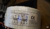
have a look at the PSU schematic from the manual - Diver300 kindly posted the relevant image earlier on.
It shows two simple windings configurable for 115 / 230V plus a fuse in the feed to the start of the first winding.
Everything appears as if just adding a replacement fuse across the appropriate two connections (as Diver300 arrowed them) should work OK. At that time, we had not seen the transformer label though.
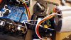
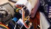
You could cut the white, but not the brown - that is the main power feed in to one of the transformer windings!
You need to add a new wire from where the brown connect on the voltage selector to the new thermal fuse, then one from that back to where the white wire goes at the power input - or use the existing white wire that comes from there.
so ifg I undersrtand this correctly, i could remove the white wire, open the brown wires sleeve, connect a new wire from the newly opened brown wire to an end of the fuse, and attach the other end of the fuse to the white wire?
so ifg I undersrtand this correctly, i could remove the white wire, open the brown wires sleeve, connect a new wire from the newly opened brown wire to an end of the fuse, and attach the other end of the fuse to the white wire?
Yes. You should not connect to the end of the white wire that goes into the transformer. You should connect to the end of the white wire that goes to the power switch.
(I would leave an inch or two of white wire coming from the transformer. You shouldn't need it ever, but it's a good idea to leave just enough to connect to in case there has been a misunderstanding an it is needed).
Can you photo the wires and I can draw in what you need to do. If I don't, someone else will. Edit - I think your photos are OK. I'll try to draw something on them.
I've had a better idea. Just open the insulation on both the brown and the white wires. Do not cut the copper in either of those wires. Connect the thermal fuse between the brown and the white wires, using extension wires if needed. Fix the body of the fuse to the side of the transformer. Tape up the brown and white wires separately and tie all the wires securely. Don't touch anything when powering it up.
(My thought is that if you can open the insulation on the brown wire, you can do it on the white wire, and you don't have to worry about which bit to connect to.)
Post a picture of the repair before you power up if you want it checked.
Im confused, as there's only one white wire going to and from the transformer, so if i opened the white wire at the power switchit wouldnt be anywhere close to the transformer.
from one end of the fuse to the other im not getting any resistence, and from one end of the wiring to the other im not getting any resistence, but from the power input im getting infinite restitence
the power pin on the right (i belive that would be the white wire) shows no resistence on the fuse, but the left pin shows me infinite resistence.
EDIT : both exposed wires without the fuse show no resistence when connected with MM leads
flipping the power on seems to work when checking with MM.. I have not plugged AC in yet. shouldn't i get no resistence from both pins? have i connected the wrong white wire? the white wire im connected to is going from transformer to power switch., the other white wire is going from power switch to AC.
This site uses cookies to help personalise content, tailor your experience and to keep you logged in if you register.
By continuing to use this site, you are consenting to our use of cookies.