Continue to Site

Welcome to our site!

Electro Tech is an online community (with over 170,000 members) who enjoy talking about and building electronic circuits, projects and gadgets. To participate you need to register. Registration is free. Click here to register now.

  • Welcome to our site! Electro Tech is an online community (with over 170,000 members) who enjoy talking about and building electronic circuits, projects and gadgets. To participate you need to register. Registration is free. Click here to register now.

How to power on this weird circuit?

Zestfully4

New Member
I have a pre-assembled DIY project I am working on for the sake of practice, and I'm perplexed as to how to power it on. Below is the schematic.

Based on it, VCC is on pin 7 of U2 and GND is on pin 2. However, the U2 component is not a typical IC as it's a board…

I have a 4.5V power source but can't seem to find a way to connect it to this circuit. I tried different combinations of red-black to one of the pads of the board and had no results. I'm a beginner student, so please be wary of that. Attaching circuit pictures from different sides below.

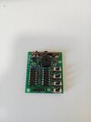
Screenshot 2024-07-27 at 08-02-25 Pro Zestaw do nauki lutowania 4 x układy DIY KIT - Sklep Opi...png
 

Attachments

  • 2024-08-24-10-34-43-406.jpg
    2024-08-24-10-34-43-406.jpg
    1.5 MB · Views: 64
  • 2024-08-24-10-34-49-068.jpg
    2024-08-24-10-34-49-068.jpg
    1.7 MB · Views: 61
  • 2024-08-24-10-37-19-596.jpg
    2024-08-24-10-37-19-596.jpg
    1.6 MB · Views: 61
  • 2024-08-24-10-37-28-599.jpg
    2024-08-24-10-37-28-599.jpg
    1.8 MB · Views: 57
  • 2024-08-24-10-39-29-599.jpg
    2024-08-24-10-39-29-599.jpg
    1.5 MB · Views: 60
It appears to be the two pads marked + and - next to Q1.

To confirm that, see if there is a copper track (on the underside of the PCB) from the + pad to the non-banded end of D3 diode, just near the connections?
 
Who can read what it does from the schematic? besides switch ABCD. No Caps but it must make funny BCD noises.
 
Last edited:
Hello all

Sorry if it is offtopic, I'm just trying to understand how control logic on this module works.
This control circuity was clear enough for me at first sight:
Keys A,B, C,D (or external input) followed by 4011 + 4066 set logic level at U2's inputs F1, F2 and
total resistanse between U2's pins #8 and #9,
and U2 should provide 16 sound effects.

But after I re-drawn control circuity with logic gates explicitly shown, and followed the circuity logic, I found that there is can only be 12 different sound effects instead of 16.
(sound effects when C = high and D = low as for me seems the same when C = high and D = high ?)

Here is my analysis attempt:

Control circuity re-drawn
SoudEffectControlLogic.png


Input-output table
LogicTable.png


Can you confirm, does this circuit work like expected?
(Does it provide 16 different sound effects?)

I can't find mistakes in my re-drawn circuit by myself... need another person to rewiev.
Can somebody confirm, is my re-drawn circuit and boolean math correct?
 

Attachments

  • SoudEffectControlLogic.png
    SoudEffectControlLogic.png
    73.1 KB · Views: 32
It looks a micro-Moog with AM-FM etc. but not nearly as clear as the desc.

Someone had a good imagination for names

0000: Machine gun voice
0001: Fire truck voice
0010: Ambulance voice
0011: The police car voice
0100: Crickets sound
0101: Alarm
0110: Electronic signal sound
0111: Koh
1000: Insect song
1001: Whistle
1010: Telegraph sound
1011: Bird song
1100: ChongJi gunfire
1101: Car sirens
1110: Bass instruments sound
1111: Racing sound

Recheck wiring of D. You may be right, Something is missing
1724701611585.png


KD9561 selection chart2


more junk https://andymurkin.wordpress.com/tag/circuit-bending-3

reminds me when I was living with a musician buddy I grew up with who had one of the 1st drum machines and I uploaded a file onto the machine to have the sound of "Heh" from a once-famous musician.
 
Last edited:
Socket J1 is clearly labelled as the power input, 4.5V-5V - polarity isn't marked, but is obvious with positive to pin 1 and negative to pin 2.
This is a DIY kit for learning, and there was no header pin included. If I don't have a header pin to install on J1, how can I power it on?
 
This is a DIY kit for learning, and there was no header pin included. If I don't have a header pin to install on J1, how can I power it on?

Solder wires in the holes, or get a header pin if you want - I've have a heap of spare two pin ones, remnants from larger strips cut down that I can't bear to throw away :D
 
What Nigel said. In the upper-right corner of one of your pics there are two holes where it looks like a header should be installed, marked + and -. If you don't have any header pins, then just solder fat wires in these holes and use them as attachment points for the power inputs.
 
, how can I power it on?
Use your skills to put a tiny slide switch in series with the wires and use hotmelt, silicon or PU to strengthen the wire joint from breaking over time and fasten neatly. (Strain relief)

1724804619655.png
 
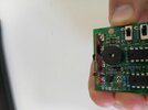
I've soldered two wires in place and tried to power on.

The wire is thin since the through-hole isn't wide, but it conducts 200V.
2024-09-0618.32.403394207476092693413.jpg

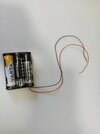
I can't get it to work. The batteries got hot first since there was a short, but I've fixed that and measured no continuity. Now nothing happens when connecting the respective terminals of battery pack and power input.

Please help.

2024-09-0618.31.177568010274146607251.jpg
 
Have you connected it the right way round?, red to +ve and black to -ve, at the lower right there seems to be a black wire connected to the +ve, and a big piece of the piezo melted away.
Yes, of course. I tried the other way around too.

You mean the wire that's for +ve attachment? As for the melted piece, I did it when trying to power on... I tried a couple times before doing that, so I would not bet that's the culprit.
 
Yes, of course. I tried the other way around too.

You mean the wire that's for +ve attachment? As for the melted piece, I did it when trying to power on... I tried a couple times before doing that, so I would not bet that's the culprit.
If there's not something immediately obvious to an educated eye, I don't feel competent enough to troubleshoot the entire PCB for potential issues. It was fun practicing some soldering on it though!
 

Latest threads

New Articles From Microcontroller Tips

Back
Top