Continue to Site

Welcome to our site!

Electro Tech is an online community (with over 170,000 members) who enjoy talking about and building electronic circuits, projects and gadgets. To participate you need to register. Registration is free. Click here to register now.

  • Welcome to our site! Electro Tech is an online community (with over 170,000 members) who enjoy talking about and building electronic circuits, projects and gadgets. To participate you need to register. Registration is free. Click here to register now.

250 watt grid tie inverter build

Status
Not open for further replies.
And yea sorry about the small and some what blurry print. It was the best I could come up with for converting the schematic from SIMetrix to a format that this website will take.
Anyway we could get electro-tech to set up the download function to take EMF files directly?
I dont care for the blurring either.

Or is ther a better way of converting the EMF format to a clearer style?
 
bbhs I can read it now (nothing changed on my end) I'm guessing TCM uploaded a new pic.
 
I tried a different approach to the format conversion on my end. And reposted the schematic. But I didn't see any change on the posting though.
I guess it must have worked after all!
 
The thumbnail didn't change, when I click the image, I can read it.
 
I just reposted the schematic notes in the actual post text.
Just in case the blurry text Nazi's come around! ;)
 
It wasn't blurry tcm =) I don't mind blurr, I seriously couldn't read it =)
 
With the text notes gone, the schematic scaled better. The schematic is easy to understand. Thanks!

Earlier schematic wasn't exactly blurry, but symbols and letters were about two pixels high. We could blow it up, but all we saw was enlarged two pixel characters. All fixed now.
 
Just trying to please everyone! ;)
First people want full and complete schematics and then I give them one and after format changes it translates as being too small to read! :(

It looked fine on my duel 30" HD monitors! :D

I will try to keep the schematics larger and easier to read even if that means having to break them up at times.

Does the independent schematics followed by block diagrams work Okay for every one?
 
Sort of yes and no.
If your referring to just building the "12 volt 250 watt GTI" Honestly no. :(
I changed the running voltage and wattage on mine.
I just put new 8.5 ft blades on my wind generator about two weeks ago and had to rebuild the old GTI to run with the higher power and different voltage. I built a 30 volt 1000 watt. And modified the existing control circuits (same ones in the posted schematics though) to work on the new voltages. (to save time) Yea I cheated a bit! ;)

SO technically, no I did not build the 12 volt 250 watt version. :eek:

The schematics and control systems I posted are identical to the actual ones I originally built though.
But as I mentioned in the posts relating to each circuit there are specific component values that I purposely left the values blank because the end builder has to match them to the actual system they have built themselves.

I felt that this would give people a wider range of substitute components and in a way make them think Little bit about how each part functions and interacts with each other.

If you find gross errors on my part due to a misprinted schematic or feel I am overlooking some critical information please let me know.

I fully admit translating a schematic from hand printed notes to a actual computer drafting system (that I am still learning) and using an actual home made circuits for references does leave me with a good chance for a schematically misprinted circuit, an omission , or occasionally a flat out F up on my part! ;)

So my full apologies if needed! I do make mistakes and overlook things fairly often! :eek:
 
hey tcmtech,

As far as the schematics go, you may consider the old microsim/pspice. For my work, I use a different editor but for those garage projects pspice can't be beat. Cadence killed it off (switching everyone to Orcad) but the last rev (v9 or v10) is a really stable platform. Fetch the student version from:

**broken link removed**

Now if you had some information on those transformers (inductance, turns) then I could whip up a simulation of the circuit you are using so the people here could tweak around with different switches, etc.
 
Now if you had some information on those transformers (inductance, turns) then I could whip up a simulation of the circuit you are using so the people here could tweak around with different switches, etc.

You mean you cant get your fancy program to work with "fair quality general purpose transformer" as a parameter?! :p

I have no actual idea what the power transformers I used actual winding numbers are. Same with the control transformer/s.
The actual ones I used fit into that just lying around category so I assume most other builders stuff will too.

If you have a wall power pack with around a 10- 12VAC 100ma output laying around see if you could come up with any rational numbers from it.

Same with the power transformer. If you have or can get a hold of a 20 amp battery charger or a 250 VA general purpose transformer, see what you can come up with based on a generalized guess.

I do have an LCR meter but I honestly have never trusted the actual L part of it! Known fixed values have never shown correctly. Some read way low others way high but few are ever close to the actual marked values.

I will take some readings on the transformers I have and see what values I can come up with.

Sorry I cant help you out much more. After all this is still a very generalized design. Its intended to be more of a road map to building one. Its rather like those somewhat generalized schematics you find for other projects. The concept and basic layout is there but the actual part matching and fine tuning is still up to to the actual builder.

I would however like to see a simulation based on what ever you think are reasonable numbers.

If you or any one else is building one feel free to post what your using and the actual simulation results or real life testing related to it. ;)

This build is for everyone, so anyone can jump in at any time and show off what you have came up with! Or what dismally failed and went up in smoke too! :(
I know some of the people that are reading this have some super back grounds in electronics design so if any of you can see a good way to fine tune this design feel free to speak up and put your name on this one too! :)
 
What I have found is the control transformers are 12 VAC 100 Ma 4VA 90uh
Unknown turns.

The power transformer is 12 VAC 250 VA 4 uh give or take. 60 - 80 turns best guess.
 
Tcm

You said that push pull type only two igbt/mosfet center pole transformer system generate lot of harmonics.
I can see that is posible especially, if shut off fets when lot of amps running. (end of cycle, when volts go zero)

But if shut off occur when grid is high and suply voltage is less than secondary normal operation voltages. I see that current is stopped at that point and shut off is save.
That kind of device cosine looks capasitive. I see also good efficiency potential (???)

Supply voltage should keep in some level less than secondary volts, that runnig current have time to stop. after that shut off fets are save. No big stop currents so less harmonics.


So control transformer circuit needs modify to give only rising edge signal. Some cap + opamp circuit maybe suitable.

if add tunable latence circuit it is posible tune rising edge start point so power feed come tunable.

It is also posible to add current sensing device to to tell when shut off is save.

Or use components like thyristor include that beheaviour build in. (circuit come little dangerous if feed voltage come too high..)
Nothing come more simple than two big thyristor and big transformer or only coil if you direct connect to grid.. (that type devices are used here, big undersea DC line ~500MW GTI..)

I just find that thread. I had long time thinking GTI stuff, but syncronization broblem never solved me before. Separate transformer, how lol I can be. It is so obivious. I had thinked AC motor + brush motor combinations etc. to do work.
With this information you can reduce that motor stuff only one line driven syncronous motor runnig commutator brush set and make it big enough to 100KA or what you need. Cheap as soap compared to IGBT desing when things come big.
Commercial GTI units are too expensive to get any profit. I pay 11.2 eurocents/kw. I have very old mechanical kwh meter, it is quite sure two way device. I don't know is it legal or not, but I don't care. Maybe grey area?.

But many thanks for tcmtech. You way may change world

EDIT:
Oh, two thyristor desing needs two diodes too, too fast thinked. But still simple.
Hmm, and if use SCR:s it don't need diodes..
 
Last edited:
Glad I could point out the obvious!:D
Too often people want to over complicate stuff! :(

I have a small push pull design posted as the tiny GTI unit thread. I have used the push pull design before but it has some limitations and the efficiency is by design rather low.
You are absolutely correct on the going mechanical when you get to the big power levels! I have worked around what is called a Ward - Lenard system before. Its used on coal mine drag lines. Its capable of multi megawatt power conversion in both directions. Going from full three phase AC to DC as a power source and then from DC back to three phase AC during regenerative braking. All within a few degrees of phase angle. ;)

That was what inspired me to design a small solid state version of it. The GTI is just the DC back to AC part.
The two transformer design was the simplest and most basic way I have ever been able to come up with that produced reasonable power transfer from DC to AC and still gave a returned power that was clean enough to be easily filtered and provide a clean sine wave on the retuning power aspect.
If you have read my posts in this thread and the other GTI threads on this forum you would get a fair idea of the how and why details behind the actual operation. And why it can be so simple yet work well.

The biggest efficiency loss in these designs is in fact the power transformer. I have seen many people thinking about using a HF step up system but I dont see any great overall efficiency gains from it yet.
A high efficiency DC-DC converter system is typically 85- 90% efficient, But so is a good quality IE iron core transformer.
A very expensive DC-DC converter will get up to around the 95+ % efficiency area but then again a good quality toroid core type transformer does too!;)
The DC-DC conversion system is smaller, lighter and more compact but also more complex and thusly less reliable in the long run. :(
My overall opinion on GTI setup is, as far as I have ever seen alternative power sources are fixed point not mobile so what does it matter if a GTI weighs 40 pounds per KW instead of 10?:p
Big, rugged, and simple takes far far more abuse before it gives up!:D

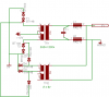
By changing from the direct control transformer drive design to a simple Mosfet or IGBT drive IC the H-bridge switching devices can be turned on and off with very little wasted power and the entier control circuit can then be ran off one very small transformer or even a line coupled power system.;)
Once that type of control IC and circuit is in place its input signal can then be manipulated any way you want in order to give you full control over current or voltage limits or anything you may desire.;)

I am glad people are reading this stuff and putting some honest thought into it! That was the whole purpose of the long write ups, to make people think and understand the basics. After they know the basics what they build upon those foundations is entirely up to them! ;):)

I could have just handed out a full and complete schematic but then people would just blindly build it and not really think about how and why it works.
To change the views of others who may then change the world in a positive way is a wonderful thing! :)
 
I mean this type unit. Components are some random from eagle library, but if replace thyristors SCR, like S0802MH there is no need for diodes and slight more efficiency (no 0.7v drop). I have pile of S0802MH:s accidently buyed as triacs.. 200uA triggers.. 8A up 800 volts..
Transformer volts needs to be more than supply and trigger circuit need more components to give single adjustable trigger point.
SCR/thyristor shut off gently when phase come high because supply is ~½ voltage from transformer high.
This type circuit push power to grid rising edge so it is capasitive load.

What think is it usable if supply is kept low enough. How think about harmonics? I see it is guite gentle switch. Add some more coils and it come more gentle.

ps. eagle is good cad/pcb program. Free version is only board size limited and it run on linux. (</linux user>)
 

Attachments

  • GTI.png
    GTI.png
    8.2 KB · Views: 2,589
Last edited:
I am not actually sure what your going for. D1 and D2 are reverse of the SCR's they are associated with and will prevent any power from being switched.

I have never gotten SCR's to work as a reliable GTI switching device. They turn on easily enough but getting them to turn off on the back side of the wave from is the problem. There are ways to do it but several more inductors transformers and capacitors are needed to make it work and that all takes away from any possible efficiency gains to be had by using SCR's

Half and full H-bridge switching systems using transistors, Mosfets, or IGBT's are simple rugged and have far better control capabilities.
SCR's have the design problem of not being able to be turned off on command. When the wave form changes from rising to falling they will keep conducting right past the zero point on the back side of the wave and just keep right on going onto the reverse side of the wave. Thats very bad!
They work well for AC to DC conversion but do not work well in the reverse usage. If that makes any sense.

Their inability to be turned off at a specific point is the whole limitation.
Starting the turn on point low on the wave and then having the wave peak greater than the input voltage will turn them off but you are very limited on the available power you can possibly transfer that way. The most efficient and also peak power transfer is when your input voltage is about 5 -15 % above the peak voltage of the transformers primary side, switched side on a GTI not line side.
 
> am not actually sure what your going for. D1 and D2 are reverse of the SCR's
> they are associated with and will prevent any power from being switched.

Ups, I did schema too quickly, they should be reverse and deny bacwards current.

> SCR's have the design problem of not being able to be turned off on command

Yes and consume zero keep open energy after triggred. Low conduct resistance too.

H bridge have two silicons, so double loss (not real broblem). Silicon cost, but minor broblem too. lot of simpler than H bridge.

> When the wave form changes from rising to falling they will keep conducting
> right past the zero point on the back side of the wave and just keep right on
> going onto the reverse side of the wave. Thats very bad!

But think if you use 24v transformer and 12v supply voltage. When wave rises, it have only first 1/4 less than 12v. During that keep SCR open. Coil have some current runing and continue some amount over 12v, but current go zero and SCR off before wave got top point.
Right?
And that SCR close is smooth operation so it produce low harmonics and low loss.

> Starting the turn on point low on the wave and then having the wave peak
> greater than the input voltage will turn them off but you are very limited on the
> available power you can possibly transfer that way.

Power transfer is definitely less. I agree. Only 1/4-1/2 of time power feed is posible.
But usually you find big enough transformer for low cost and use of cheapo tyristors/SCR:s reduce cost. Less silicon to blow up..

So what you think is harmonics broblem in that kind of device or not? How about efficiency? You had play these for long time. Do you have tested suchs device?
Is it worth of try (I can find 90% parts of my junkstorages)

Thanks
 
Status
Not open for further replies.

Latest threads

New Articles From Microcontroller Tips

Back
Top