Continue to Site

Welcome to our site!

Electro Tech is an online community (with over 170,000 members) who enjoy talking about and building electronic circuits, projects and gadgets. To participate you need to register. Registration is free. Click here to register now.

  • Welcome to our site! Electro Tech is an online community (with over 170,000 members) who enjoy talking about and building electronic circuits, projects and gadgets. To participate you need to register. Registration is free. Click here to register now.

Grid Tie Inverter Prototype

Status
Not open for further replies.

Val Gretchev

Member
Forum Supporter
The world is rapidly running out of fossil fuels. Once fossil fuels are all depleted, that’s it – we go back to the dark ages. People are already preparing for a world without oil. Here is the worst case scenario: **broken link removed** . This is reminiscent of the people in the 60s who built all those fallout shelters. I prefer to think that there is another more optimistic option. Humanity’s salvation will be to harness the only remaining sources of energy. They are fission – as in Uranium, and fusion – as in deuterium / tritium reaction. Fission reactors are well known and there is more Uranium out there to last a hundred years. Deuterium/ tritium can be obtained from sea water and there is enough for several thousand years. The problem with fission reactors is that they produce waste products that have to be stored for thousands of years. People don’t understand the safety aspects of reactors and want to close them down. Germany announced just recently that it’s shutting all of its reactors by 2022. They got scared when Japan’s nuclear reactors were damaged by the earthquake. Fusion reactors also make everything around them radioactive. However, the radioactivity only lasts a few weeks. Sustaining a fusion reaction to produce electricity reliably is at least 50 years away (**broken link removed**). In the mean-time, there is only one fusion reactor that works, and that is the sun. In the next 50 years or so, it has to be the source of energy to bridge the gap from fossil fuels to fusion reactors. I won’t be around to see the transition to fusion energy production. But solar power in the next 8 to 15 years can potentially buy us some time.

A good YouTube video about where energy comes from and where it’s used is the following: https://www.youtube.com/watch?v=m1BogqElenA

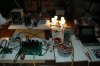
Here is an inverter project I have been working on for some time. It’s still not complete. There are some shortcomings in the design. The inductors have to be bigger and perhaps the output IGBTs should be a bit faster. So far, I have only been able to push it to 400 Watts and then the boost inductors get too hot. I have only operated it off-line so far. I made an error on the pin-outs of the current measuring modules and got them reversed. I wish the vendors would only show their device pin-outs from the top! I will have to build another prototype to finish the tests. It’s an expensive hobby but other people spend a lot of money on skiing, golfing, etc.

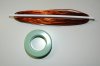
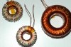
I recently ordered some powdered iron toroid cores and will be winding some larger inductors. The magnetic components are the only items not readily available off-the-shelf.

The software seems to work well controlling the device but the AC PLL algorithm still has to be written so that I can try it on-line. Also, the MPPT and anti-islanding algorithms have to be developed.

I hope these documents can be of use to someone.
 

Attachments

  • GTI_July_30_2011.zip
    2.5 MB · Views: 1,181
It’s an expensive hobby but other people spend a lot of money on skiing, golfing, etc.

Very nicely done. If this is your hobby, I can only imagine what your work looks like.
 
Dear Gretchev,
this is a very complete work, rarely is possible to found people sharing time and knowledge like you, I'm also of your idea and I love share my knowledge with others.

I've see your schematic just now after posting my first three thread into this forum:

https://www.electro-tech-online.com/threads/grid-tie-inverter-schematic-2-0.105324/#post1009741

my original idea was to setup a small power inverter suitable to be mounted n a single slar module backpanel then I've worked around a solution with a single stage conversion (I don't have the Boost stage between the solar module and the power inverter and the MPPT work by controlling the output current as you can see from the schematic).

Into the simulation I've written in C language the FSM and the MPPT module if you like I can share the code.
Also I kindly ask you if you can write a summary of your microcontroller code, just a simple flow chart in order to see what approach have used to sequence the start of the inverter operation. This may help to speed the code reading and to have a forma mentis about the flow. Hope you can did it.

Also I read about some software PLL, I'm also looking and study about digital PLL realization inside the microcontroller and if you like we can talk on the subject and other stuff.
As a first approach to stay synchronized with the grid you can use a simple grid sensing on operational amplifier or some isolated modue and use this feedback signal after light filtering. If the line is not very noising the system should be able to work and for starting test avoid the use of a digital PLL.

About the antiislanding there are several way to did it, at first a simple passive scheme must be implemented, over and under voltage and over and under frequency detection, but is also prefereable use active scheme like the frequency jump (needed if there are more than a single inverter paralleled on the grid), and I'm also looking and reading from paper how implement this latter into the software.

Regarding MPPT I'm using a code that I've read in a thesis work and seems work nicely into the simulation then I hope also into the real life :). If you like I can share my full inverter code, no problem.

The only problem that I can think about full-bridge topology with line frequency transformer is about the transformer core saturation, do you've think about this?

Anyway very impressive work! I'm now actually investigating what is the best topology for single panel mount, but you're very away with your design !!

If you like I can setup some simulation stage to test the microcontroller code.

Happy to see other people share my same passion for power electronics!!

Best regards
Powermos
 
Last edited:
GTI State Machine Diagram

Here is a diagram of the state machine that senses the push button switches and starts the inverter. As you can see App.c has changed since my last publication. It is continuously changing as I test the circuit board.

I also added a second state machine that implements a simple MPPT algorithm using the Perturb and Observe method. I have not tested this routine.

ATD.c now has MonitorAC routine which locks the inverter to the power line.
 

Attachments

  • GTI_Oct_14_2011.zip
    241.9 KB · Views: 700
Here is a diagram of the state machine that senses the push button switches and starts the inverter. As you can see App.c has changed since my last publication. It is continuously changing as I test the circuit board.

I also added a second state machine that implements a simple MPPT algorithm using the Perturb and Observe method. I have not tested this routine.

ATD.c now has MonitorAC routine which locks the inverter to the power line.

Thank you Val for your time and the infos provided.
Regarding the MPPT that I've implemented into the simulator I've used the code proposed into the attached paper and seems able to work nicely also for rapidly changing solar irradiation condition.

Regarding your schematic I can understand that you've used a Boost interleaved structure as a front end for the power converter in order to step up the solar module voltage to a level which is greater than the maximum peak line voltage. Then the inverter stage is a full bridge topology equipped with IGBT. The external inductor in your schematic is responsible to filter the switching frequency component from the output current before inject it into the grid, also the output capacitor act as a filter in the same sense.
The grid side current sensor sense the injected grid current and I think you use it in order to implement a closed loop current control to achieve the output current in phase with the grid voltage (to reach a power factor close to 1). I've to admit that at this time I don't have see all your source in detail in order to see the control strategy then I kindly ask you if you can let me know what type of controller strategy have used to keep the output current synchronized with the grid voltage.

In my simulation (substanctially the my simulated topology is the same you used with the only difference that you boost the panel voltage using the first Boost stage) I've used a current loop and the compensator was a simple proportional gain. I've choose the optimum gain value by studying the small signal model of the inverter wich is basically a single pole system (attached).

Could you please let me know what consideration you have did in order to proper sizing the control loop?

In attachement I've put my simple thinking that I've did to obtain the model of the controlled system and the pole frequency formula.

Thank you.

Best regards
Powermos
 

Attachments

  • paper-MPPT.pdf
    253.4 KB · Views: 806
  • Small-Signal.pdf
    66.1 KB · Views: 736
Last edited:
Prototype Limitations

As I stated in my original post: I made an error on my board with the pins of the current sensor modules and burned them out. It was too difficult to patch up the board, so I haven't implemented any current control loop yet until I build another board. I tried to do as much debugging as I could with the existing board. Therefore, I have not yet been able to close the relay and go on-line with this inverter.

I did learn a number of things with my first prototype and will probably change the design considerably if and when I make my next board. The DC to AC stage will probabley be similar to the design in the attached partial schematic.

It's nice to see that you are using control theory to design your inverter code. I have taken a simpler (seat-by-the-pants) approach and, using only a minimum of math, built a prototype to test my theories. I was hoping that a simple controller could do the job without resorting to a DSP with much greater mathematical capability. However, I did separate the power circuits from the microcontroller board so that I could exchange it with a faster and more sophisticated processor.
 

Attachments

  • InverterVer2Partial.pdf
    41.5 KB · Views: 771
Inverter control

Hi Val,
thank you for your infos upgrade.

About the control loop I'm thinking to implement it in analog way and use a small microcontroller only for the MPPT and FMS tasks. Also regarding the PWM generator I'm thinking to use a classical TL494 or equivalent.

About the control loop, for the first inverter idea (the high frequency full-bridge with line frequency transformer), I've see that a simple proportional gain was enough to achieve a good tracking of the current reference.

Actually I'm seriously thinking to do a practical build of the simple Flyback current fed topology (liested on the other thread) instead the Full-Bridge in order to mount it directly on the back panel of the solar panel, of course for the topology limit reason the maximum power will be limited around 200 W.
Regarding the inverter behaviour the Flyback work in DCM (Discontinuous Mode) and the inductor has been calculated in order to achieve the DCM behaviour over all the valid power range of the converter. The advantage of this topology is that only one switch is high frequency driven (on the primary side) the output bridge is self commutated by the grid and then is not affected by switching losses, only conduction losses.

Actually I'm working around the control loop because I've don't see in literature (IEEE paper) the analysis of this converter from the control point of view, only open loop analysis. Now I'm giung to investigate the inverter behaviour from a simulation point of view then I'll check to make some analysis from the control theory.
My idea is to take the full rectified waveform of the rescaled main voltage and then multiply it with the output that came from the MPPT algorith (filtered PWM from the microcontroller), at this point I've to send this value to the PWM modulator. To perform the analog multiplication I'm thinking to use the low cost AD633 analog multiplier and the TL494 as PWM modulator. In order to obtain the full wave rectified from the main a simple ideal rectifier with two OPAMP (you can see the idea on the other thread). The microcontroller (a simple PIC16F877), as I write above, is only for the FSM, anti-islanding and MPPT then just to execute slow tasks. May be into the future I'll going to implement full in digital by means of a dsPIC or TMS320 low cost DSP (the latter is very often used in various IEEE paper).

Regarding the numerical simulation of the Flyback I've attached for your reference the schematic and the waveform, as you can see the KM signal is representative of the MPPT algorith output and track nicely the maximum power from the solar module (signal PMPP equal approximatively to 160 W for4 the solar module that I've modeled), the two block is the MPPT and the inverter FSM, this two block can be build by means of a small microcontroller (the MPPT algorithm is executed every 100 ms, the state machine every 1 ms then this is a slow tasks), the other circuitry is mainly for grid sensing, solar module voltage and current measurement and to perform the analog multiplication between the grid voltage and the MPPT signal. The two comparator on the right side of the schematic is used to drive the output unfolding bridge (M1, M2, M3, M4), this MOSFET are used only as switch to commuitate the current in a synchronous way respect the mains voltage. The choose of the MPPT task time execution was did by the converter dynamics, in other word I've did some test, basically just change the KM of one step and see the amount of time needed to the input power to reach the new steady state value, the MPPT time must be choosed greater than this time, that's all. About the FSM the execution time should be keep less than the minimum time request to perform the anti-islanding condition in order to react in a time that is compliant with regional main rule.

Now I'm also reading about the active antisdlading protection. About this stuff I'm try to implement the active frequency jump. To did this I've to setup a PLL and I've some idea by using a CD4046 followed by a function generator as the XR2206 then add a voltage reference into the loop in order to force the PLL to shift away the output frequency when the grid is lost. Alternatively I can try to put inside the microcontroller a digital PLL like your that I've see into the source code. About this I kindly ask you if you've some detailed infos/description about the logic used to kept it synchronized with the grid. As I've said actually I've not read in a deeper detail your source code and then if you can provide to me some hint about this stuff I can speed-up my understanding of your code and solution.

Could you please let me know what type of control you like to use in your inverter and what is your approach to this aspect? I'm like to learn more about this amazing things.

Thanks in advance for your kindness.

Best regards
Powermos
 

Attachments

  • Flyback-Simulation-Schematic-MPPT.pdf
    77.5 KB · Views: 688
  • Flyback-Simulation-Waveform-MPPT.jpg
    Flyback-Simulation-Waveform-MPPT.jpg
    230.7 KB · Views: 845
Last edited:
Sine Wave Generator

You can find more information on the sine wave generator and synchronization to the power line by going to my Post5.zip in "Grid Tie Inverter Schematic" page 17.
 
PWM Module and execution time

Dear Val,
I've read the code from the post5.zip and I understand the logic, the set interrupt time was 1/30kHz and every cycle the code perform the table scan and the amplitude calculation for the new value to put inside the PWM generator.

I've just to question:

1. what is the overall execution time for the code inside the ISR? In other word what is the total amount of time taken to execute all the code inside the PMFC_Reload_Int? I need to this infos in order to make some comparison with my microcontroller, I'm thinking to use a PIC micro and I've to do some consideration regarding the execution time in order to choose the right microcontroller in fact I've to execute the ISR in some time and then leave some time free in order to perform the other task. If the execution time take too long my risk is to enter continuously into the ISR and then have no more time to execute the slow task inside the main code.

2. regarding the amplitude modulation I've see that the Amp variabile can span from 0 to 255 then the resul of the calculus SineValue*Amp/255 will span from 0 to a maximum of 200*255/255=200, this is to fit the 8-bit size due to the architecture of your micro regarding the multiplication and division.
Now suppose e.g. to have a small Amp value, like 10. In this situation we have at the maximum of the sinewave 200*10/255=7 (rounded integer value). Then for a SineValue between 0 to 200 the SineValue*Amp/255 calculation give us a value between 0 to 7 hence a sinusoidal wavefor with only 7 step between 0 and the peak. What is the effect of this segmentation on the inverter output signal? Of course this effect should be mitigated from the fact that the signal has small amplitude, just to know in practice what is the situation.

Thanks in advance.

Powermos
 
Last edited:
AC Generating Interrupt Routine

1. Here is the disassembled PMF.c code with cycle times for each instruction. You can add up the values for various paths through the interrupt routine.

2. The value "SineValue*Amp/255" is then added or subtracted to/from "Modulus/2". Modulus is define in PMF.h as 400 for a 60Hz system. You are right in a way I should prevent the final calculation from going to 0 or 400. That can be easily done by changing the IncAmplitude and DecAmplitude routines. I'll have to check this carefully some other time.
 

Attachments

  • PMF.asm.pdf
    104.6 KB · Views: 754
AC Generating Interrupt Routine

Thank you Val for the reply,
could you please let me know what is the single instruction execution time for the microcontroller that are you using? (alternatively if you can and have some time simply take the direct measure with the oscilloscope of the total ISR time by simply toggling a output pin on the start and the end of the ISR code).
In this way I can calculate the overall execution time of the ISR code, sorry I've missed to insert also this request into the my previous mail.

Also could you please let me know the overall resolution of your PWM hardware module?

Regards
Powermos
 
Last edited:
CPU Bus Clock

The 8 MHz crystal is converter to 24 MHz by the microcotroller PLL which is the core clock. The Freescale manual states: The core clock signal is the clock for the CPU. The core clock is twice the bus clock as shown in Figure 4-18. But note that a CPU cycle corresponds to one bus clock. Therefore, the bus clock is 1/2 of 24 MHz so, one CPU cycle is 83.333 ns.
 
Revised Bus Clock

I always get confused with the clock on this microcontroller and the manual is not very clear. I believe the Bus Clock is 24 MHz when set according to CPU.c.

You will have to calculate the time in the interrupt routine manually. I am in the middle of another project and have dismanteled my inverter setup.

My rough calculation indicates that the ISR takes approximately 3.41e-6 seconds while 33.33e-6 seconds are available.
 
Last edited:
Revised Bus Clock

Thank you Val for the infos.

Also I've did some calculation and time is accordingly to your estimation, is a more powerful microcontroller respect the small PIC16F876 ;-) in fact with the PIC16F876 I'm able just to make a exact replacement of the common PWM generator TL494 working at a frequency of 20 kHz. In a 50 us I can make the AD conversion of the voltage input and drive the PWM with the converted voltage. After this task I've no more time to do other task.

I've also tried to approach the synthetized sine waveform solution but I can't perform the multiplication and division in a reasonable execution time due to the absence of the on board hardware multiplier then actually I'm looking for another microcontroller type like the PIC18F4431, this one is equipped with a 8x8 hardware multiplier and have a internal PLL in order to get it working up to 40 MHz.

Could you please let me know the last things about the your microcontroller PWM resolution?

Thanks in advance.

Best regards
Powermos
 
Last edited:
PWM Resolution

There are 2 PWM circuits in this microcontroller.

The PWM that drives the boost circuit is an 8-bit counter set to increment from bus clock / 2 = 12 MHz. The period register is set to 0xFF. Therefore, the PWM generates pulses at 46875 Hz. The flip-flop for the interleaved boost circuit divides this by 2 producing approximately 23.4 kHz for the boost IGBTs. The duty cycle for each IGBT varies between 0 and 50%. Therefore the resolution is approximately 42.6 microseconds.

The PMF that drives the H-bridge is a 15-bit counter. It is driven by bus clock / 2 = 12 MHz. The period is 400 pulses for a 60 Hz system so the interrupt frequency is 30,000. For a 50 Hz system, you would use a period of 480 pulses for an interrupt frequency of 25,000 Hz. The resolution of the PMF is approximately 33.3 microseconds for a 60 Hz system and 40 microseconds for a 50 Hz system

You can learn more about this microcontroller from the attached manuals.
 

Attachments

  • MC9S12E128V1.pdf
    3.1 MB · Views: 719
  • S12CPUV2.pdf
    5.7 MB · Views: 623
Dear Val,
thank you very much for the datasheet and the explanation.
I'll try with the PIC18 and I will report some news.

Best regards.
Powermos
 
Custom Inductors

As I mentioned earlier, the inductors had to be custom wound. Fortunately, I found a Switching Converter Power Supply Calculator at the following URL:
https://www.daycounter.com/Calculators/Switching-Converter-Calculator.phtml
Also see Boost Converter Design Equations.

I found a source for the Powdered Iron Toroidal Cores made by Micrometals. Their URL is: https://www.micrometals.com/
In their Design Tools tab you will find a program: Inductor Design Software 2010 (MicroRelease_March2010.exe) which is handy to predict the parameters of the inductors using Micrometals cores.

The cores were obtained from Loadstone Pacific at the following URL: https://www.lodestonepacific.com/index.php
The cores are relatively inexpensive but they have minimum quantity requirements which brings the cost up considerably.

After several attempts, I settled on the following designs:
H-bridge filter inductor: Micrometals T400-40D core. Two layers of wire wound around the core for a total of 176 turns #14 AWG wire. Measured inductance was 7.17 mH.

Boost Inductors: Micrometals T250-52 core. 44 turns of #14 AWG wire spread out on 1 layer. Measured inductance 438 uH.

The wire was obtained from Applied Magnets at the following URL: https://www.magnet4less.com/index.php?cPath=9
See Essex Magnet Wire 14 AWG Gauge Enamel - Model# AWG14-200C-11

The wire was first wound on a bobbin and then transferred to the cores (see pictures).

To secure the wire ends, I used a high temperature Kapton tape I obtained from Digi-Key: 3M541312-ND

The picture shows the inverter driving four 120 Volt 100 Watt light bulbs connected in series-parallel with a pure sine wave through an isolation transformer.
 

Attachments

  • DSC_2908.JPG
    DSC_2908.JPG
    432.3 KB · Views: 789
  • DSC_2927.JPG
    DSC_2927.JPG
    413 KB · Views: 845
  • DSC_2918.JPG
    DSC_2918.JPG
    372.9 KB · Views: 1,236
Status
Not open for further replies.

Latest threads

New Articles From Microcontroller Tips

Back
Top