Continue to Site

Welcome to our site!

Electro Tech is an online community (with over 170,000 members) who enjoy talking about and building electronic circuits, projects and gadgets. To participate you need to register. Registration is free. Click here to register now.

  • Welcome to our site! Electro Tech is an online community (with over 170,000 members) who enjoy talking about and building electronic circuits, projects and gadgets. To participate you need to register. Registration is free. Click here to register now.

2 relays, 1 photo switch, linear actuator 12v

Status
Not open for further replies.

whitt3rx

New Member
Please bare with me, circuits are very new to me.
I am wanting to wire up an automac chicken coop door that uses a photo switch. I watch a couple YouTube videos. Well mine doesn't work...
I have (2) 4 pole relays (my understanding was that this was to create reverse polarity)

1 12v phot switch with 3 wires (red, black, white) (the white wire is gray in my diagram)

1 linear actuator with 2 wires (red, black)

I have attempted to draw out the circuit, if some could help me finish the wiring I would be most appreciative.
Or tell me how to fix it?
Thank you
James
 

Attachments

  • IMG_3077.JPG
    IMG_3077.JPG
    38.6 KB · Views: 117
We don't all have chicken coops. You need to tell us exactly what it is that you want the circuit to do.

The relay contact points on the relay also need some labelling. Some contacts are also missing. a DPDT relay should have 6 contacts (2 to switch the first main current, 2 to switch the second main current, and 2 to control the entire relay.)

Also, please tell us which polarity makes the linear actuator extend and detract.

We also need more information about your photoswitch. There are many types and some types can't work alone.
 
Last edited:
Thank your response
On the linear actuator if you put red to the negative post and black to positive it extends, reverse and it closes.

I want to the the photo switch to retract the linear actuator when the sun comes up, and extend the linear actuator when the sun goes down
 

Attachments

  • IMG_3078.JPG
    IMG_3078.JPG
    41.9 KB · Views: 108
  • IMG_3079.JPG
    IMG_3079.JPG
    171.4 KB · Views: 127
linear actuator
More information. Pictures? My linear actuators have there wires. One is common and one UP and one is Down. This kind stops when it hits the ends. They are good for 600 pounds, will kill a chicken)
I also have one kind that power makes it go up but a spring makes it go down. (5 pounds)
Some are 12V DC and some are 24VAC and others are 110VAC.
Some kinds do not stop at the end.
 
Those relays you have are Single-pole, single-throw relays. You will need four of them to reverse direction through your linear actuator if it only has two wires coming out of it. If it had three wires then you would be able to use the relays you have.

Alternatively, you could use two single-pole, double-throw (SPDT) relays or a one double-pole, double throw (DPDT) relay
 
I beleive that you need some basic information on how to draw a schematic - single line diagram, so I have mixed together some links that should provid help:

1. Use correct symbols.
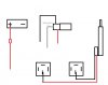
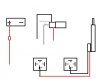
As you probably hav seen from feedback, your initial drawing make little sense to anybody exept yourself. So I found this site that have a large collection of all kind of symbols.
http://eidetec.com/electrical-disconnect-symbol

2. Some guidelines about single line drawing and explanation.
Haven't read through this stuff myself, but it seems to be something you can learn from
**broken link removed**

3. Now that you have read - just some more stuff
Probably just repeat, but less to read, older schematics (like from bad scan jobs). Those two color drawings is just terrible to look at, but gives this nice feeling from the 90's. The link pints somewhere in middle of a short course. From a educational standpoint I haven't relly looked at it.
http://www.nzdl.org/gsdlmod?e=d-000...z&cl=CL1.3&d=HASH01f889f8eb8a8df4aa452841.7.5
that was a really long url, could it be due to using google search and redirected?

4. The juicy stuff
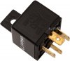
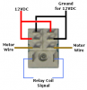
If you got to understand relays and contactors, this is the logic next step. How to make control circuits.
http://www.ibiblio.org/kuphaldt/electricCircuits/Digital/DIGI_6.html

5. Draw nice
I do not know what program you used to draw - frankly I think I don't want to know either. Using old MSpaint or similar dull raster graphic software tend to make any schematic really ugly.
Personally I use Inkscape for most drawings. It is a general purpose vector drawing program, so you just draw any components at will and may duplicate it all over the place if so.

Comment about drawing software [post edit]: I just spend some minutes searching the web for non-comercial software for drawing such single line diagram, but with no luck as it seems most of that kind of software is comercial. Maybe that is just me that had not find a good enough search phrase..
Anyway - Inkscape will always be on my short list because - exept for the obvious, it can produce nice drawings and smooth lines - it is made for both Windows, Linux and mac. Downside - it is not a electrical schematic drawing program, typing just that I hope someone on this forum know about one.
 
Last edited:
I am gonna check and see if I can find one at the auto parts store. If not will this one work?
 

Attachments

  • IMG_3080.PNG
    IMG_3080.PNG
    323.9 KB · Views: 108
I am gonna check and see if I can find one at the auto parts store. If not will this one work?
That should work.

What we're going to end up with is basically something like this:


You may want to grab a 0.1uF X5R or X7R ceramic capacitor and a 2W to 5W resistor that is 1 to 5 ohm while you're at it. To be honest, you could probably get away with 1/4w or 1/2W resistor since this motor only switches twice a day rather than many times per second so the resistor won't heat up much. This is just because whenever a motor turns off it can "kick" and make an arc which can wear down your relays a bit whenever they try to turn the motor off. These two components can be used to help tame things a bit.

We need more information about the photo-switch.

Also, like Ron was saying, we need you to confirm that the linear actuator has a limit switch at both ends so that it stop on it's own when it hits the end (rather than continuing to drive itself and burn itself out). Things get quite a bit more complicated if this is not the case.
 
Last edited:
5. Draw nice
I do not know what program you used to draw - frankly I think I don't want to know either. Using old MSpaint or similar dull raster graphic software tend to make any schematic really ugly.
Personally I use Inkscape for most drawings. It is a general purpose vector drawing program, so you just draw any components at will and may duplicate it all over the place if so.

Comment about drawing software [post edit]: I just spend some minutes searching the web for non-comercial software for drawing such single line diagram, but with no luck as it seems most of that kind of software is comercial. Maybe that is just me that had not find a good enough search phrase..
Anyway - Inkscape will always be on my short list because - exept for the obvious, it can produce nice drawings and smooth lines - it is made for both Windows, Linux and mac. Downside - it is not a electrical schematic drawing program, typing just that I hope someone on this forum know about one.


https://www.digikey.com/schemeit/project/
 
Probably getting ahead of myself, but the photo switch I bought has 3 wires on it. Assuming the DPDT relay looks like this, where do I attach the wires from the photo switch too? (Red, black and white)
 

Attachments

  • IMG_3081.PNG
    IMG_3081.PNG
    35 KB · Views: 139
That's a DPDT relay and it looks like there are 6 power contacts. Which is one for each pole. Each pole has a common pin, and the other two pins are a normally closed and normally open pin.
The way the relay works is that you put a small current through the relay coil which is an electromagnet. The electormagnet pulls the main power contacts of the relay closed or open to let the larger power current flow.

The photoswitch will make some kind of connection to the relay coil contacts. The reason I asked about the details for the photoswitch is because we need to know exactly what it does and outputs becuase that will decide how it connects up to the photoswitch. Depending on the photoswitch you may need another component to make things work.
 
That would be the red and black wires I assume, so where does the white wire go?

I'm not familiar pinout of industrial photoswitches but looking at the photos of them online:

Load = Red
Line = Black
Neutral = White

Neutral, White -> Battery negative and one relay coil pin
Load, Red -> the other relay coil pin
Line, Black = Battery positive

Similar to the schematic at the bottom of this page:
**broken link removed**

These photoswitches blocks or allows current to flow between red and black. At the same time, the photoswitch steals the current it needs to power itself and that current flows from black to white. I'm not sure if your photoswitch is like that or not.

Part of the reason I was asking for info about the photoswitch was because I did not know if photoswitches needed a power supply to run themselves or whether they had completely separate contacts for their power supply (four pins), or if they had one pin shared for their switching and power (3-pins), or if they even needed a power supply at all (2-pins).

Or if they had a normally open and a normally closed contact just like the relay which would add on another pin to all the previous configurations.

Some photosensors are able to run passively and do not need an external power supply but I was unsure if industrial photoswitches could get away with that. For example, I have some pressure switches that need no power supply but have 3 wires because one is common, one is normally open, and one is normally closed. But it could just as easily have been that they need a power supply and only have a normally close contact which would also be three wires.

For the resistor and capacitor I was mentioning earlier, put them in series with each other and put that combination in parallel with the motor. This is called an RC snubber. Putting them closer to the relay is better (dampens both the motor inductance and the wire inductance) but it doesn't make a big difference if you put it closer to the motor since most of the inductance is in the motor anyways and not the wire.
 
Last edited:
Thank you for sharing your knowledge. I must admit that electrical diagrams do not make much since, but I think I can wire this up now.
 
Status
Not open for further replies.

Latest threads

New Articles From Microcontroller Tips

Back
Top