Continue to Site

Welcome to our site!

Electro Tech is an online community (with over 170,000 members) who enjoy talking about and building electronic circuits, projects and gadgets. To participate you need to register. Registration is free. Click here to register now.

  • Welcome to our site! Electro Tech is an online community (with over 170,000 members) who enjoy talking about and building electronic circuits, projects and gadgets. To participate you need to register. Registration is free. Click here to register now.

Solenoid actuator to push a button

Scoops

New Member
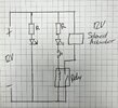
Hi folks, I'm wondering if anyone could point me in the right direction. I am trying to build a device to push a button for me using a solenoid push actuator. Would the attached circuit work?

I'm sure there is a better way of doing it? And pointers would be great I'm not traditionally an electronics guy.

Thanks
 

Attachments

  • IMG_3618.jpeg
    IMG_3618.jpeg
    1.3 MB · Views: 134
You want a diode across relay to limit switch arcing :

1722857185975.png


If your relay coil is rated for 12 V no need for series R. Also
why do you have a series diode ? Not sure why thats needed.

Do you want, after release of button, relay to stay on ? Latch ?
Eg. one push relay stays on, next push relay stays off. If so use a
latching relay.


Regards, Dana.
 
Having a resistor and LED in series with the relay coil severely limits the number of relays you have to choose from. The odds of the relay coil going open circuit are extremely low. Since you already have an LED indicator showing that the circuit has been powered, I would eliminate the one in series with the coil.

And add a suppression diode as in the other answer.

Next, select the solenoid and post its characteristics (voltage / current / power). Once you have this, we can guide you in selecting the relay.

Any particular reason you are not driving the solenoid directly with the switch?

ak
 
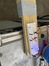
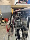
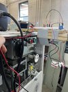
Hi Guys, thanks for the replies. I have the circuit made on a breadboard now.
The reason why I don't want it working directly with a switch is that when I get this working from a mechanical perspective I will move on to using a remote control with it so I can have the button pushed from outside the room for remote switching of a 10kV transformer.

Unfortunately my solenoid isn't strong enough to push the button when the spring is charged.
 

Attachments

  • IMG_3632.jpeg
    IMG_3632.jpeg
    2 MB · Views: 116
  • IMG_3633.jpeg
    IMG_3633.jpeg
    1.6 MB · Views: 123
  • IMG_3629.jpeg
    IMG_3629.jpeg
    1.7 MB · Views: 139
Hi Guys, thanks for the replies. I have the circuit made on a breadboard now.
The reason why I don't want it working directly with a switch is that when I get this working from a mechanical perspective I will move on to using a remote control with it so I can have the button pushed from outside the room for remote switching of a 10kV transformer.

Unfortunately my solenoid isn't strong enough to push the button when the spring is charged.
You are likely losing current at each contact because of the high resistance of the spring steel breadboard and the 26-gauge DuPont wires used as jumpers. I don't know what your power supply looks like but I wouldn't count on more than 1 Amp through a breadboard - if your power supply can power an amp.
 
If the button contacts or wires are accessible and mention the output voltage & load on the button, there may be better semiconductor solutions than electromechanical solenoids. They look like big buttons that operate at low current to internal power latches. But It could be something else. The fewer mechanical Rube Goldberg's the better.
 
Last edited:
But looking closer appears to be an expensive dual power button (on/off) assy.
Your measurements would help.
1722874371479.png


A mechanical finger needs to be a firm short push with little or no gap and not a fast punch that might crack the colored PVC.
The solenoid and relay need a reverse diode across all DC coils to catch the flyback arc.
The force drops quickly with extension, so add a suitable extension for a very short stroke and about 10 to 20 watts for 1/4 second. (much longer and it gets hot) Then it should work for a 3 oz button. Adjust gap to minimum.
 
The OP can put a stiff(ish) piece of rubber or a stiff spring between the actuator pin and the button to simulate a human press rather than the hammer blow of the actuator pin.
 
1722882552190.png

Needs to touch button on centre , relaxed with better alignment.
 
Use a servo pushing on a spring which then pushes on button. Spring allows
for mechanical tolerances without overload electrically or mechanically.

Here is an application using network to push a button with a RC Servo -


Regards, Dana.
 
But looking closer appears to be an expensive dual power button (on/off) assy.
Your measurements would help.
View attachment 146626

A mechanical finger needs to be a firm short push with little or no gap and not a fast punch that might crack the colored PVC.
The solenoid and relay need a reverse diode across all DC coils to catch the flyback arc.
The force drops quickly with extension, so add a suitable extension for a very short stroke and about 10 to 20 watts for 1/4 second. (much longer and it gets hot) Then it should work for a 3 oz button. Adjust gap to minimum.
Thanks for the input Tony. No there is no access inside the unit. Normally there is a front cover. I am trying to create a tool which can portable and be used on any of several hundred of these switches as required.

The buttons are a mechanical release to a spring loaded mechanism closing a 10kV switch. So they are quite hard to press when the spring is charged.
 
The buttons are a mechanical release to a spring loaded mechanism closing a 10kV switch. So they are quite hard to press when the spring is charged.
OK so your buttons open/close a 10KV switch gear. That said what exactly are the buttons switching? Meaning what voltage and current do the buttons make and break? In the image posted it looks like you have access to the rear of the buttons.

Next if you want to do this using a solenoid as mentioned you choose a solenoid based on required force to push the button and allow overhead on the needed force. Using a solenoid I would think about using a MOSFET for low side switching, that's an N Channel MOSFET. You can find endless schematics of MOSFET switching solenoid on line. I just don't see using a mechanical solenoid as a good solution. I am also assuming the button press is momentary. Depending on your switchgear.

Ron
 
Ok so with a 10kV switch, the travel will be greater, but you still want to minimize compressing the spring or cut it as the magnetic force is greatest in the retracted position.

You may exceed the solenoid's rated voltage 50%~100% easily if used for minimum duration with the return spring cut ( using the switches spring) and adjusted for the minimum gap with a solathane (damped rubber) coated tip, operated ideally with a 1-shot pulse.

A threaded-mounted solenoid can be fitted to a stiff "L" bracket to the unit's button bracket.

I'd be surprised if this solenoid wasn't firm enough on a short stroke at 7.9W 12V with no gap. 5 mm throw.

Stroke : 2mm, 450gf,5mm, 250gf
1722897365223.png


Use a "logic level NFET low-side solenoid driver with diode instead of relay rated for >=5A.
 
OK so your buttons open/close a 10KV switch gear. That said what exactly are the buttons switching? Meaning what voltage and current do the buttons make and break? In the image posted it looks like you have access to the rear of the buttons.

Next if you want to do this using a solenoid as mentioned you choose a solenoid based on required force to push the button and allow overhead on the needed force. Using a solenoid I would think about using a MOSFET for low side switching, that's an N Channel MOSFET. You can find endless schematics of MOSFET switching solenoid on line. I just don't see using a mechanical solenoid as a good solution. I am also assuming the button press is momentary. Depending on your switchgear.

Ron
Hi Ron,
The buttons don't switch anything. A handle is turned charging a spring mechanism and the buttons just release the mechanism to close or open the 10kV switch. The switchgear has no voltage except the 10,000 V.

Thank you, I'll look into that MOSFET.
 
I believe the switchgear automates the motor/gear rewind coil and the rapid release uses the stored spring energy instead of a much larger solenoid to release the high velocity contactor to minimize arc transition energy.

These are just the mechanical latching push buttons. Imagine the out/in power gain.
 

Latest threads

New Articles From Microcontroller Tips

Back
Top