Franknstein
Member
Hi all, hope someone can point me in the right direction with the circuit i've built. I'm not an electronics engineer or anything, dabbled in a couple of cicuits and stuff over my lifetime, mucked about with Dick smiths beer powered radio's and stuff like that.. this is the first cicuit of any complexity (to me at least) that I've designed.
I basically do a lot of car racing simulator component building as a hobby, and until now, interfacing with already made joysticks and USB devices has been pretty easy as I just take them apart and wire in remote switches to the circuit boards to perform what I need to do (ie. make a pseudo gearbox out of wood and stuff, and have 6 microswitches at each gear gate, which close the circuit on each corresponding button on the joypad)... you get the idea I'm sure.
Now, I bought this premade gearshifter for sim racing the other day, and its really old, and features some weird cartidge system and a DIN plug of sorts. I dont have anything to plug that specific DIN plug into my pc, and need it to be USB.
The shifter works in the following way:
1 2 3
|_|_|
| | |
4 5 6
(it has gears 7 and 8, but I blanked those off cos its rubbish)
The shifter shaft works exactly like a cars one does.
Now, see my post here: **broken link removed**
Something important to note is that when in neutral, obviously none of the microswitches in the shifter are closed...
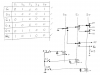
3rd and 4th gear are easy because they are either the 'green' or 'blue' wires independantly.... but 1,2 and 5,6 are combination switches... AND - when you move the shifter to the left side it will activate the microswitch with the yellow wire first, then when you shift into 1st or 2nd it activates either green/blue wire together with the yellow... what i'm saying here is that I dont want the yellow wire (or the red wire for the right hand side gears (5,6)) to activate any button on the remote USB joystick.... So my whole thinking was to break the circuit into three sections:
1. -green/blue are normally closed (Activated) when in Neutral.
-red/yellow circuits are deactivated
2. -when yellow is activated (circuit now knows its moving to left axis)....
-deactivate green/blue for remote gears 3 and 4
-activate circuit green/blue for remote gears 1 and 2.
-all circuits on red wire (right side of gearbox, ie gear 5 & 6) are
deactivated.
2. -when red is activated (circuit now knows its moving to right axis)....
-deactivate green/blue for remote gears 3 and 4
-activate circuit green/blue for remote gears 5 and 6.
-all circuits on yellow wire (left side of gearbox, ie gear 1 & 2) are
deactivated.
Well, thats how it makes sense in my head, I hope someone here can follow my logic and really look forward to a response that could be of any use. After all the hours I've put in and it doesn't work (on the pc, it works with my multimeter set on CONTINUITY, testing each gear) I am really dissapointed.
I tried drawing up some logic charts with XAND/XOR symbols that I remember from computer science and just could not wrap my head around the logic of it that way....
Look forward to any reply!
Thanks!
Ryan
I basically do a lot of car racing simulator component building as a hobby, and until now, interfacing with already made joysticks and USB devices has been pretty easy as I just take them apart and wire in remote switches to the circuit boards to perform what I need to do (ie. make a pseudo gearbox out of wood and stuff, and have 6 microswitches at each gear gate, which close the circuit on each corresponding button on the joypad)... you get the idea I'm sure.
Now, I bought this premade gearshifter for sim racing the other day, and its really old, and features some weird cartidge system and a DIN plug of sorts. I dont have anything to plug that specific DIN plug into my pc, and need it to be USB.
The shifter works in the following way:
1 2 3
|_|_|
| | |
4 5 6
(it has gears 7 and 8, but I blanked those off cos its rubbish)
The shifter shaft works exactly like a cars one does.
Now, see my post here: **broken link removed**
Something important to note is that when in neutral, obviously none of the microswitches in the shifter are closed...
3rd and 4th gear are easy because they are either the 'green' or 'blue' wires independantly.... but 1,2 and 5,6 are combination switches... AND - when you move the shifter to the left side it will activate the microswitch with the yellow wire first, then when you shift into 1st or 2nd it activates either green/blue wire together with the yellow... what i'm saying here is that I dont want the yellow wire (or the red wire for the right hand side gears (5,6)) to activate any button on the remote USB joystick.... So my whole thinking was to break the circuit into three sections:
1. -green/blue are normally closed (Activated) when in Neutral.
-red/yellow circuits are deactivated
2. -when yellow is activated (circuit now knows its moving to left axis)....
-deactivate green/blue for remote gears 3 and 4
-activate circuit green/blue for remote gears 1 and 2.
-all circuits on red wire (right side of gearbox, ie gear 5 & 6) are
deactivated.
2. -when red is activated (circuit now knows its moving to right axis)....
-deactivate green/blue for remote gears 3 and 4
-activate circuit green/blue for remote gears 5 and 6.
-all circuits on yellow wire (left side of gearbox, ie gear 1 & 2) are
deactivated.
Well, thats how it makes sense in my head, I hope someone here can follow my logic and really look forward to a response that could be of any use. After all the hours I've put in and it doesn't work (on the pc, it works with my multimeter set on CONTINUITY, testing each gear) I am really dissapointed.
I tried drawing up some logic charts with XAND/XOR symbols that I remember from computer science and just could not wrap my head around the logic of it that way....
Look forward to any reply!
Thanks!
Ryan