Franknstein
Member
Thanks Eric.
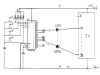
Like this: ?
**broken link removed**
notice common of now named switches y1-y6 (S1-S6 were confusing me as they share the same name as S1,S2,S3,S5 to the left of my diagram) is not connected to anything anymore, its just as it was on the USB joystick board from the factory, and does not share continuity with my 0V GND wire.
Is that correct now? I want to be sure, before I do something wrong and blow something up")
Also, whats wrong with using the meter btw?
tnx again
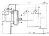
Like this: ?
**broken link removed**
notice common of now named switches y1-y6 (S1-S6 were confusing me as they share the same name as S1,S2,S3,S5 to the left of my diagram) is not connected to anything anymore, its just as it was on the USB joystick board from the factory, and does not share continuity with my 0V GND wire.
Is that correct now? I want to be sure, before I do something wrong and blow something up
Also, whats wrong with using the meter btw?
tnx again