Continue to Site

Welcome to our site!

Electro Tech is an online community (with over 170,000 members) who enjoy talking about and building electronic circuits, projects and gadgets. To participate you need to register. Registration is free. Click here to register now.

  • Welcome to our site! Electro Tech is an online community (with over 170,000 members) who enjoy talking about and building electronic circuits, projects and gadgets. To participate you need to register. Registration is free. Click here to register now.

Dummy Load II

Status
Not open for further replies.
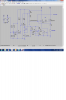
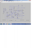
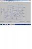
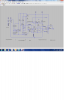
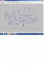
Hi (). Yes, your right the drop across the ammeter will make the current look higher to the circuit the way it is. We could move the ground for the reference to the top of the meter I guess. I think the meter needs to be on the ground side for the voltmeter part to work. There wasn't a spec on the meter Jeremy posted, but a similar one quotes 1 milliohm. So I think it is a hall sensor rather than a shunt. That kinda makes since because even a 50 millohm shunt at 100 amps would drop 5 volts and dissipate 500 watts.

I think it will run ok at 48 volts. You will need to double the voltage on the TVS but I think the FET is good for 100 volts. The way it is set up I don't think you can dissipate to much power because the adjustment only goes to about 62 and 31 amps resectivly.
 
Lets move the ground for the reference as well.
 

Attachments

  • DL2.png
    DL2.png
    149.8 KB · Views: 234
Thanks ronv! I think I am going to have some time on my hands to get building it over the next couple weeks. Of course I need to order the parts first. I'll let the new schematic marinade for a day or two and make sure we don't change anything first.
 
Good plan. On third thought, lets do it like this:

Same parts, it's just that ground for the logic is on the other side of the ammeter. The ones labeled logic ground are all tied together.:rolleyes:
 

Attachments

  • dl3.png
    dl3.png
    144.6 KB · Views: 218
Lets make one last tweek to get rid of the crossover distortion by adding a 6.2k to the output of the op amps.
There I think we are good to go.:rolleyes:
 

Attachments

  • dl4.png
    dl4.png
    159 KB · Views: 217
So, I wanted to step through the schematic before I order parts to make sure I understand everything. I have a couple questions for ronv regarding the schematic in the post above (post 366):

1. Comparing the Dummy Load I (DLI) to Dummy Load II (DLII) there are some differences, so I just want to make sure I am understanding it correctly. One difference I noticed is the auto shut off for over temp logic has more parts then DLI, some of which appear redundant. I am guessing you probably did this on purpose to add stability, or something...anyway, that's not really a question, more just an observation. The question I have is it looks like the positive feedback loop of U3 is connected to +24v through a 39k resistor (R14). Is this +24v the device under test (DUT) or a separate +24v power supply meaning I would have 3 power supplies, +12v, +24v, and the DUT? If it is the DUT, will it mess it up if I connect a +48v DUT?

2. Again, I have total confidence that you know what you're doing, I am just questioning for my own understanding sake and to double check...on DLI the +12v was connected to the positive feedback input of U4 (U1 in the original DLI, U4 of DL2) through a resistor, R5, and the temp sensor was connected to the negative feedback of U4. In DLII this is flipped with +12v connected to the negative (instead of the positive) through 91k resistor and the temp sensor to the positive. I am guessing this doesn't matter and it can be connected either way, correct?

3. Just want to confirm that V1 is a temperature sensor.

4. What does the line coming out of V1 with a +12 at the end of it represent? I don't think this is a connection directly to +12v because that just doesn't make sense, so it must mean something else.

5. Lastly, DLI had a way to get a read out to a voltmeter where 10 volts = 100C off the temp sensor. Though it's not required, it is nice to be able to visually see what the temperature is. I know it will function on it's own by shutting down once it's too hot and then coming back on again when it cools whether or not I can see what the temp is, but it is nice to know how close I am getting to the upper temp limit. Is it possible to put a visual temp reading into the schematic without too much trouble?

OK, I think that should do it for now, I think that is all the questions I have. I am going to go to Fry's Electronics now and try to find a non-conductive case to put it all in. I'll hold off on the BOM until tonight.
 
So, I wanted to step through the schematic before I order parts to make sure I understand everything. I have a couple questions for ronv regarding the schematic in the post above (post 366):

1. Comparing the Dummy Load I (DLI) to Dummy Load II (DLII) there are some differences, so I just want to make sure I am understanding it correctly. One difference I noticed is the auto shut off for over temp logic has more parts then DLI, some of which appear redundant. I am guessing you probably did this on purpose to add stability, or something...anyway, that's not really a question, more just an observation. The question I have is it looks like the positive feedback loop of U3 is connected to +24v through a 39k resistor (R14). Is this +24v the device under test (DUT) or a separate +24v power supply meaning I would have 3 power supplies, +12v, +24v, and the DUT? If it is the DUT, will it mess it up if I connect a +48v DUT?

Yes, It is a little different. The circuit on the left with U3 is the circuit that detects when the DUT is above about 30 volts. It is a comparator so it just turns on when that happens and cuts the current in half. The 24 volt label is the DUT so anywhere from 12 to 48 volts. The circuit with M3 shuts off the current and sounds the alarm.


2. Again, I have total confidence that you know what you're doing, I am just questioning for my own understanding sake and to double check...on DLI the +12v was connected to the positive feedback input of U4 (U1 in the original DLI, U4 of DL2) through a resistor, R5, and the temp sensor was connected to the negative feedback of U4. In DLII this is flipped with +12v connected to the negative (instead of the positive) through 91k resistor and the temp sensor to the positive. I am guessing this doesn't matter and it can be connected either way, correct?

When I changed to M3 it took the opposite polarity to turn it on so I also "flipped" U4 so everything works the same.

3. Just want to confirm that V1 is a temperature sensor.

4. What does the line coming out of V1 with a +12 at the end of it represent? I don't think this is a connection directly to +12v because that just doesn't make sense, so it must mean something else.

Yes, V1 is the temperature sensor. (LM35) I noticed I didn't show the +12 on the original so I added it. I'm thinking you must have hooked it up in the original??

5. Lastly, DLI had a way to get a read out to a voltmeter where 10 volts = 100C off the temp sensor. Though it's not required, it is nice to be able to visually see what the temperature is. I know it will function on it's own by shutting down once it's too hot and then coming back on again when it cools whether or not I can see what the temp is, but it is nice to know how close I am getting to the upper temp limit. Is it possible to put a visual temp reading into the schematic without too much trouble?

Good idea. I added it back in.
 

Attachments

  • DL5.png
    DL5.png
    164.4 KB · Views: 224
Yes, It is a little different. The circuit on the left with U3 is the circuit that detects when the DUT is above about 30 volts. It is a comparator so it just turns on when that happens and cuts the current in half. The 24 volt label is the DUT so anywhere from 12 to 48 volts. The circuit with M3 shuts off the current and sounds the alarm.

Ah, I see...I knew there was something going on over there. Cool, that makes sense...I am glad you included that feature!

Thanks also for adding the temp read out.

Now as I am building the BOM, I am noticing that a couple components like 2N7002 and STB120NF10 listed in the schematic seem to only be available in surface mount instead of through hole (I think you mentioned something about that a few posts back). I am searching around for through hole components that will work.
 
btw...I picked up a cool acrylic case from Fry's to put it all in. It's transparent with a blue tint. I am thinking I will add some LED lights for effect :)
 
I noticed I didn't show the +12 on the original so I added it. I'm thinking you must have hooked it up in the original??

Yes, you are right. I forgot, but I went back and looked at it and I did have to connect the third connection of the temp sensor to +12v.
 
You can use a 2N7000 instead of the 7002. Use the same FET you used last time. I has a little better spec than the one I used in the simulation. And yes any of the 324's are ok.
 
Ooops

I hope you haven't ordered parts yet cause I made a mistake. Maybe not so bad they are probably Radio Shack parts.
 

Attachments

  • DL6.png
    DL6.png
    145.7 KB · Views: 222
Nope, haven't ordered yet. I have been doing some research on circuit board layout techniques. I am a little overwhelmed by the amount of info out there...I have been reading this:

https://www.electro-tech-online.com/custompdfs/2013/06/sloa089.pdf

I don't know if you can shed some light on this subject...i.e. what do I really need to be concerned about? I was beginning to wonder if the placement of parts on the circuit board could be causing the interference.


Here is an crude drawing of the basic idea I was thinking of how to lay out the parts this time. Does anyone see any problems with this layout? It is the copper pipe in a square around a large PCB with the FETs soldered to it and the logic circuitry for each FET as close to its respective FET as possible. I will somehow have to get +12 volts out to them and ground, oh yeah, and the POT that adjusts gate voltage.
 

Attachments

  • 001.jpg
    001.jpg
    295.6 KB · Views: 234
maybe a good start would be to keep the logic ground and the DUT ground seperate. I mean, last time I built the dummy load I just had one 10AWG wire I soldered to the PCB and connected all the grounds to it, logic and DUT alike. In actuality, the grounds will still be electrically connected because they will all be plugging into the same wall socket, but I wonder if having them in such close proximity and being connected to the same exact wire for ground can cause interference?
 
For laying out a good solid circuit of this type, a basic rule of thumb is simply to try and keep all your connections as short and direct as possible. This often times means that certain connections may have to take the loss of being lengthened somewhat, in order to gain much shorter connections elsewhere, or everywhere. It is a lot of optimization and tradeoffs, you may not have a good idea what the best configuration is until after you have actually seen what it all looks like put together. So.. make sure you mock things up a few times before you start soldering. And don't be afraid to undo some things and go back a few steps if you think it can make some stuff shorter. I usually fight for every mm of routing that I can, it's always a good thing. The schematic can help too, but only if it also has been drawn with the shortest connections possible in mind, which isn't always the case.

Basically...
Keep all the connections short as possible, this could help immensely with problems like noise and stability.

Keep wires thick, especially power wires. It will reduce certain kinds of issues. Ground loops for one.

Keep sensitive logic and control wires away from the main power wires, it's usually fairly important.


The most important things to keep as short as possible in this particular circuit are probably all the op-amp's input connections. This means, from the op-amps to the gate of the MOSFET, and from the control signal for the pot to the op-amp. Also keep them well away from power wires. Assume they will pick up the magnetic fields of these power wires and they will see that as some kind of control signal.
 
Status
Not open for further replies.

Latest threads

New Articles From Microcontroller Tips

Back
Top