Electro Tech is an online community (with over 170,000 members) who enjoy talking about and building electronic circuits, projects and gadgets. To participate you need to register. Registration is free. Click here to register now.
Welcome to our site! Electro Tech is an online community (with over 170,000 members) who enjoy talking about and building electronic circuits, projects and gadgets. To participate you need to register. Registration is free. Click here to register now.
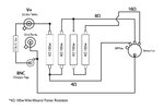
I wanted to design a general purpose load box for electronics projects but also wanted it to be enough for audio use.
Can someone see if my wiring/setup for this is correct? Any problems or alterations for my intended purpose.
The resistors are rated for up to 5 A, but it may be less or more than that, depending on the duty cycle and the heat sink. For short periods of time, the 100 W resistors can stand well over 100 W even without a heatsink, as they are quite big and take some time to heat up.
The rotary switch may not be so forgiving. I haven't looked for a rotary switch rated at 5 A or more, but you should make sure of the rating of switches you can buy.
For the resistors, use ones that are described as "non-inductive". Power resistors are almost always made of resistance wire that is spiral-wound on a ceramic core. The spiral of course has inductance. To lessen this, a non-inductive resistor has the spiral wound in one direction for half of the core, the would the other direction for the second half. For an amplifier frequency response to be truly "flat" at 20 kHz without a peaking circuit that adds frequency-dependent phase shift, it often needs a bandwidth of over 80 kHz. At those frequencies, load inductance matters.
Also, note that high-power switches sometimes have two ratings, one for switching and one for carrying. If you *never* will change switch position positions when the circuit is on, you might get by with a lower-cost switch, one that is rated maybe for 6 A carry but only 2 A switching. If a rotary switch turns out to be a problem, then three SPST toggle switches will do what you want with a (cool - ?) 1950's retro look, and 10 A industrial switches are relatively low cost.
In theory, a power amp can deliver much more power to a 4 ohm load than a 16 ohm load. Another advantage of going with toggle switches is power levels. With DPDT switches, the same resistor set can deliver these circuit power ratings:
I had to add some low value resistors in series with a big motor to simulate wiring resistance. The total current was about 60 A, so each switch had to handle around 20 A. I used toggle switches for that, and they worked fine, although they were never switched under load and have only had a few minutes use in total.
I wanted to use a rotary for ease of use, most of the time the intended use will not be for amplifiers and then only for short intervals and only for a speaker load and not at full output power.
No, I will not be switching with circuit active. It is simply a static load.
Should I be using ceramic power resistors then?
Is the wiring layout correct? It is modified form someone else's schematic
It makes no difference, they are still wirewound, however, I would suggest you try measuring their inductance - for audio frequencies, particularly at lower frequencies, the inductance is rarely a problem. Not to mention, finding non-inductive high power resistors is going to be difficult, and incredibly expensive.
Edit: I just tested a 1 ohm 7W wirewound resistor, and it reads 1uH at 200KHz. This would only be 0.13 ohms at 20KHz.
What you don't want to do, it use them for radio frequency loads
I made a audio load unit for testing audio amplifiers a few years ago. I used load resistors similar to these, except I used combinations of 16 ohm units.
Agree; did the same thing. One clear advantage is that as the load current increases with lower selected impedances, the number of switch contacts (specifically, the number of square inches of contact surface area) sharing the current increases.
It makes no difference, they are still wirewound, however, I would suggest you try measuring their inductance - for audio frequencies, particularly at lower frequencies, the inductance is rarely a problem. Not to mention, finding non-inductive high power resistors is going to be difficult, and incredibly expensive.
Edit: I just tested a 1 ohm 7W wirewound resistor, and it reads 1uH at 200KHz. This would only be 0.13 ohms at 20KHz.
What you don't want to do, it use them for radio frequency loads
Wirewound would be perfectly fine then, and considerably cheaper than non-inductive ones.
I must admit, having measure one the other day, I was surprised how low an inductance they actually were.
For a crude, cheap, option you could make your own using electric fire elements (or part of) - you used to be able to buy replacement wire elements for silica tube heaters (which you pulled through the old silica tube with a piece of string). These were cheap, and a good source of high temperature resistance wire. A full 1000W element would give you 57.6 ohms, or a 750W one 76.8 ohms, measure suitable pieces off, and series and parallel as you like.
Bear in mind, for valve amp protection, it's not critical to have the correct value load - the issue with no load at all is the potential for high voltage spikes breaking down the insulation in the transformer, and any sort of 'reasonable' load will damp it down and prevent that.
This site uses cookies to help personalise content, tailor your experience and to keep you logged in if you register.
By continuing to use this site, you are consenting to our use of cookies.