jocanon
Member
I am calling this thread Dummy Load II because I already built dummy load 1, now this is version 2. Dummy Load 1 thread was here:
https://www.electro-tech-online.com...emp-control-fan-load-bank-pwm-circuit.128753/
So the dummy load we built the first time worked great! I say "we" built because, as will see if you read the first thread, I had a lot of help from ()blivion and ronv. Thanks again guys! So, it worked great until I had to go and mess it up . I was testing the voltage on one of the op-amps and accidentally shorted the Vcc to the output while the load was connected...I know, stupid...! Anyway, that pretty much fried a few things in there. In actuality, I can still use that first dummy load, I just disconnected the damaged components. Initially there were 10 MOSFETs that burned off the current, now there are just 8...it's actually just barely enough for my purposes with 8.
So, partially breaking the first one got me to thinking that I should build a second as a back up anyway, just in case I fully break the first one someday. I run a business where I have to test power supplies on a regular basis and cannot afford to be without the dummy load and do not really want to spend thousands of dollars on one at retail.
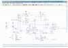
Attached to this post you will find the schematic of the original design. Essentially it is a variable dummy load capable of loading up a PSU up to about 1500 watts or so, maybe higher. I am testing two 12v PSUs connected in series for 24v that go up to about 50 amps. We bleed off the current directly through the MOSFETS instead of using PWM and burning the current in resistors. In order to cool the MOSFETS I soldered them to a copper pipe that I then hooked up to my basement laundry tub sink and I run cold water from the tap through it. I have a temperature reading hooked up to the copper line and the load will shut down if it gets above about 88C and then turns back on again once it gets back down to about 75C. An LED and alarm also will sound when the load shuts off due to getting too hot. It will only ever get that hot if I forget to turn on the water. With the water running it stays a cool 20C in the winter when loading it up to about 1100 watts and a little hotter in the summer (water is pretty cold out of the tap in the winter here in Buffalo, NY).
The other schematic I am attaching is a temperature controlled circuit that controls the fans inside the dummy load. The fans are there to provide cooling for the current sense resistors.
There are only a couple things I want to tweak in the original design:
1. I would like to make it so the current sense resistors do not get so hot. I emailed ronv and he suggested using 10 WATT resistors instead of 5 and tweaking the OHMS a little. We will also need to swap out some of the resistors for different values to get the current readings right once we change the current sense resistors.
2. Also, the voltage readings AND current readings are very twitchy, they jump around. I would like to add something to the schematic to even them out and reduce the noise so that they are a little more stable readings.
. Lastly, if possible, I would like to make the dummy load capable of 1700 watts. I think we could just add a couple more MOSFETS to increase the capacity.
I contacted ronv via email and he said he would be willing to help me make these modifications. The attached schematic was his creation, so he still has it and is working on it right now.
So this thread will be covering the build of this new slightly modified dummy load. The attached schematic is the un-modified original version. If anyone out there has any input or ideas to improve the design all are welcome.
Thanks!
Jeremy
https://www.electro-tech-online.com...emp-control-fan-load-bank-pwm-circuit.128753/
So the dummy load we built the first time worked great! I say "we" built because, as will see if you read the first thread, I had a lot of help from ()blivion and ronv. Thanks again guys! So, it worked great until I had to go and mess it up
. I was testing the voltage on one of the op-amps and accidentally shorted the Vcc to the output while the load was connected...I know, stupid...! Anyway, that pretty much fried a few things in there. In actuality, I can still use that first dummy load, I just disconnected the damaged components. Initially there were 10 MOSFETs that burned off the current, now there are just 8...it's actually just barely enough for my purposes with 8.So, partially breaking the first one got me to thinking that I should build a second as a back up anyway, just in case I fully break the first one someday. I run a business where I have to test power supplies on a regular basis and cannot afford to be without the dummy load and do not really want to spend thousands of dollars on one at retail.
Attached to this post you will find the schematic of the original design. Essentially it is a variable dummy load capable of loading up a PSU up to about 1500 watts or so, maybe higher. I am testing two 12v PSUs connected in series for 24v that go up to about 50 amps. We bleed off the current directly through the MOSFETS instead of using PWM and burning the current in resistors. In order to cool the MOSFETS I soldered them to a copper pipe that I then hooked up to my basement laundry tub sink and I run cold water from the tap through it. I have a temperature reading hooked up to the copper line and the load will shut down if it gets above about 88C and then turns back on again once it gets back down to about 75C. An LED and alarm also will sound when the load shuts off due to getting too hot. It will only ever get that hot if I forget to turn on the water. With the water running it stays a cool 20C in the winter when loading it up to about 1100 watts and a little hotter in the summer (water is pretty cold out of the tap in the winter here in Buffalo, NY).
The other schematic I am attaching is a temperature controlled circuit that controls the fans inside the dummy load. The fans are there to provide cooling for the current sense resistors.
There are only a couple things I want to tweak in the original design:
1. I would like to make it so the current sense resistors do not get so hot. I emailed ronv and he suggested using 10 WATT resistors instead of 5 and tweaking the OHMS a little. We will also need to swap out some of the resistors for different values to get the current readings right once we change the current sense resistors.
2. Also, the voltage readings AND current readings are very twitchy, they jump around. I would like to add something to the schematic to even them out and reduce the noise so that they are a little more stable readings.
. Lastly, if possible, I would like to make the dummy load capable of 1700 watts. I think we could just add a couple more MOSFETS to increase the capacity.
I contacted ronv via email and he said he would be willing to help me make these modifications. The attached schematic was his creation, so he still has it and is working on it right now.
So this thread will be covering the build of this new slightly modified dummy load. The attached schematic is the un-modified original version. If anyone out there has any input or ideas to improve the design all are welcome.
Thanks!
Jeremy