Electro Tech is an online community (with over 170,000 members) who enjoy talking about and building electronic circuits, projects and gadgets. To participate you need to register. Registration is free. Click here to register now.
Welcome to our site! Electro Tech is an online community (with over 170,000 members) who enjoy talking about and building electronic circuits, projects and gadgets. To participate you need to register. Registration is free. Click here to register now.
Thank you I have ordered the parts from SYDNEY I will let you know how it turns out after I build the Voltage regulator and install the device.
Thank you again Greg
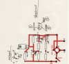
The trim pot must be between R2 and R3, with one end of R3 grounded (see my schematic).
I cant tell if I am looking at the bottom of the transistors through the layout? If so, it looks like you have two of the pins on the TL431 swapped. One of the outside pins should go to the pot wiper. The middle pin should go to ground.
On the 2n3906, if you are really using the TO-18 metal can, the pin closest to the tab is the emitter. Check the pin out. **broken link removed**
On the FET, I cant tell if I'm looking at the top or the bottom; it matters.
The 1Ohm 50W resistor should not be mounted on the board; it should be the kind that mounts on metal for heatsinking, like this.
Thank you for picking up that I had made a mistake in my board Circuit .
It was late when I finished the Board layout.
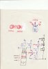
I am not shore what pins go where, could you check the attachment and let me know if they are correct or inform me where they should go with a diagram. The 2N3906 is a TO-92
I am still learning .
Thank you for your help.
sorry I am a pest.
I am trying to do the same thing, but I have an small ATC motorcycle. It puts out mid 40's at high RPM. But, if there is a current draw of any kind it might put out significantly less voltage, which is what I think it will. It has a single wire coming out, with the engine case as the other connection. I am trying to absorb these designs.
So far, I see two separate circuits, one a rectifier, and one a regulator, patched together. I take it there is no single TO-220 package rectifier/regulators available? I have a 15-45VAC output from the alternator, and am looking for 13.5VDC output, regulated. I do not know what current the alternator produces. I will check it out with my DMM.
I am trying to do the same thing, but I have an small ATC motorcycle. It puts out mid 40's at high RPM. But, if there is a current draw of any kind it might put out significantly less voltage, which is what I think it will. It has a single wire coming out, with the engine case as the other connection. I am trying to absorb these designs.
If it has only a single wire, chances are that the rectifier is build in, and that the output is actually rectified DC (pulsing with a DC component). If it really is AC coming out of that single wire, then the best you can do is add an half-wave rectifier consisting of a single high-current diode. There would have to be two wires to utilize full-wave rectification as shown in my previous posts to this thread.
So far, I see two separate circuits, one a rectifier, and one a regulator, patched together. I take it there is no single TO-220 package rectifier/regulators available? I have a 15-45VAC output from the alternator, and am looking for 13.5VDC output, regulated. I do not know what current the alternator produces. I will check it out with my DMM.
The simplistic alternators built-in to these machine can only be shunt-regulated
Take an automotive sealed-beam head-light or other high current 12V lamp, and hook it across the alternator output with the engine running at speed. The lamp load should pull down the alternator voltage to ~15V. This means that a shunt regulator will only have to absorb about the same current as it takes to light the lamp.
There actually is a way to regulate these generators other than with a shunt.
Series regulation can be achieved by replacing two of the diodes in the rectifier bridge with thyristors.
If the o/p's generator really delivers 10 Amps then an analog shunt would have to dissipate up to 140W, which can be a daunting task to keep sufficiently cool on a hot day, plus it wastes gas.
Thank you for that information. I believe it is AC voltage, I tried connecting a small DC air compressor and the motor only vibrates but does not spin. The headlight for the ATC is also not present, and when I am using the inflator I may opt to turn the headlight off.
I re-checked my work, and the voltage output is at 12 VAC near stall and around 70 VAC full throttle. The current is a consistent 3.8 amps AC.
Will your schematic work for my setup with a single high current diode?
Yes. I'm assuming that you will be paralleling a small 12V battery (like an SLA) across the output of the alternator, and the job of the shunt regulator is to prevent overcharging the battery. The circuit I posted will do that just fine. If you leave out the battery, there will be a very strong ripple, even though the voltage peaks of the ripple will be clamped at the voltage set by the regulator circuit.
What are you planning to power off the alternator/regulator?
Initially I wanted to just power the small 12v cigarette lighter inflator I have, but being able to power other things would be a big plus. I feel you are saying that plugging in a cell phone charger or GPS would be a bad idea, due to the ripple? I should use a small battery as a capacitor. Probably a good idea. I am of limited spaced on the small ATC but I am sure I could figure something out.
You will need either a battery or a large electrolytic capacitor; otherwise the average value of the output will be about 1/2 of the regulated (peak) voltage.
I'm guessing that the inflator draws more current than your alternator can produce, so a small battery would make up the difference, with the charge being replaced after the inflator is disconnected.
I have but one more question: With a steady 3.8A AC , with a varying voltage from 12-70 VAC, about how much current at 13.5VDC could I expect from a regulator/rectifier without a battery?
I have but one more question: With a steady 3.8A AC , with a varying voltage from 12-70 VAC, about how much current at 13.5VDC could I expect from a regulator/rectifier without a battery?
I'm not sure if your 3.8A measurement was into a dead short (i.e. just the ammeter), or if you were measuring the current into a 12V lamp (it makes a difference).
Assuming that your measurement supports 3.8A @12VAC, then with a half-wave diode rectifier, you would only get about 1/2 of 3.8A = 1.9A.
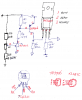
I have gone over the Circuit diagram I thing on the previous Circuit diagram that I drew I have the E, B, C 2N3906 the wrong way around but the one that I have attached to this post is correct Could you advise me if the E,B,C is correct.
I have made the board and I have placed the components on the board.
Just going through the final check.
Will place a photo of the finished project as soon as I am convinced that every thing is ok.
This site uses cookies to help personalise content, tailor your experience and to keep you logged in if you register.
By continuing to use this site, you are consenting to our use of cookies.