tundrawolf
New Member
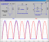
I was using just a dead short, just the ammeter.
I was thinking, if it's only 1.9A, then a battery would be necessary. However, I don't want the batter charging all the time, because of the drag it adds to the already small 110cc engine. Is there a way around this?
I was thinking, if it's only 1.9A, then a battery would be necessary. However, I don't want the batter charging all the time, because of the drag it adds to the already small 110cc engine. Is there a way around this?
Last edited: