Electro Tech is an online community (with over 170,000 members) who enjoy talking about and building electronic circuits, projects and gadgets. To participate you need to register. Registration is free. Click here to register now.
Welcome to our site! Electro Tech is an online community (with over 170,000 members) who enjoy talking about and building electronic circuits, projects and gadgets. To participate you need to register. Registration is free. Click here to register now.
If I remove the connection between the emitter of the photo coupler and just have it going to the detect , the block detector doesn't work anymore. Seems it needs the ground.
Regarding wheel resistance, most of my users model retro, as in they run cabooses (cabeese?). The general practice is to install a loading resistor in the locomotive and in the caboose, not bothering with the intervening cars (wagons).
I used 5K6 to illustrate because it is a common value for wheelsets as sold here. Using only two detectable cars per train, loading isn't an issue. Frequently, I recommend 470 ohms for the loco and caboose both. Combined, that's less than 65mA extra current. (500 ohms @ 16 volts = .032A) Insignificant..... 10 resistors @ 5K6, paralleled, would be 560 ohms. ~30mA... Perhaps better, as flicker from one car won't drop the signal.
My recommended practice is to fabricate a circuit such as you would use to light a passenger car. Metal frame trucks and conductive axles, attached to a plastic underframe. A 6mm strip of .1mm (1/4" x .0035) brass shim stock is drilled to match the bolster, for each end. Long enough to reach past the axles under the frame. Then solder a resistor between. Cheap and quick....
Looking at your signal logic circuit, it looks very familiar... Were you to analyse my elementary, I think you will find it's about the same, merely two iterations of the circuit to provide signals for both directions. Bi-directional traffic is very common here because of the distances.
Best of luck with it. Now the problem is solved, you can go play trains! Perhaps you might appreciate this:
**broken link removed**
I was in Wellington, N.Z. in the late 60's. This showed up at a convention in Aukland at the 68 meet. It made the rounds in the 70's, I'm trying to get it started back up. The older I get, the better it reads....
One last thought; I have tried simulators, long ago... They worked well for digital circuits. But now we have PICs and the like, my designs are passe'. I never had much luck doing analogue circuits with them. Perhaps two or three generations of improvements have corrected that. Much of my work has been with low level industrial instruments; a strain gage has 0-20mV full scale output. Keeping signals like that clean around welding operations takes some finagling. These days, I have a library of circuits in my head that I simply apply without thinking about them. As a novice, you probably were pulling out your hair over my comments. For that, I do apologize.
Bill Hudson
For circuit simulation the two best IMO are TINA and LT SPICE.
both free downloads.
The LT SPICE is better for digital stuff and the TINA for analog stuff. I like the interaction that TINA provides.
TRY them both out, you just mght like them.
I forgot the resistance get's less the more you add.... There's me thinking it get's bigger and eventually will not allow enough current to power the led let alone a loco!
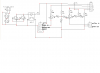
As for the led being lit by an optoisolator, the led shown won't actually be there, the collector of the photocouple connects to the detect output on the signalling circuit. When the photocoupler lights, the detect circuit is made and signal turns red (block previous to one loco is on. This in turn set's the previous block to that to yellow. If wagons stretch to that previous block, their resistors across the wheels turns that block red, and the previous one yellow.
Ta-Da
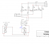
And here's the full circuit, for each block and signal.
J3 goes to block ahead of loco to switch yellow when block ahead switches red.
J2 goes to block behind loco to switch the previous block to yellow when J4 is switch by the block detector.
I'm so happy, you've all had reputation added. What a team...
Now to work out the PCB for the detector bit. That way if the detector goes wrong, I can swap just that section, likewise with the signalling part.
Er Um? That's cool when the train goes TO town, but does it come back or do all the passengers have a one way ticket. OR do you just have a circular track OR are you using double track.
Are you by any chance using the same signal circuit to drive the signals in the opposite direction? If so your opto isolator has to drive up to 4 LEDS at 15 Ma per LED. Can you sim the detector opto-isolators current limit when driving 4 LEDs at 15 milliamps each. I think it should be OK but it's worth a check.
went wild and simed up o 89.1K at 89.2 the LED goes out (off, no light, not on etc.)
he DCC voltage would have effect on this for sure.
tried varing the battery voltage from 12 - 24, didn't make any difference.
Hi MrDeb,
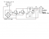
Using the DCC 16v supply at 85K ohms *about) the voltage across the diodes drop below 1.4 volts and they are effectively out of the circuit. Now the 1.4 volts is across the Twin-T. a furthe increas in track resistance drops this 1.4 volts towards the transistors PN junction minimum level (No i'm not going into it) which is around 0.7 volts. At less than 0.7 volts the transistor stop conducting. That is when the total track resistance reaches 89.1(5) K. Increasing the Twin-T voltage makes no difference. Increasing the DCC voltage would. Hope that helps.
I used 5K6 to illustrate because it is a common value for wheelsets as sold here. Using only two detectable cars per train, loading isn't an issue. Frequently, I recommend 470 ohms for the loco and caboose both. Combined, that's less than 65mA extra current. (500 ohms @ 16 volts = .032A) Insignificant..... 10 resistors @ 5K6, paralleled, would be 560 ohms. ~30mA... Perhaps better, as flicker from one car won't drop the signal.
Looking at your signal logic circuit, it looks very familiar... Were you to analyse my elementary, I think you will find it's about the same, merely two iterations of the circuit to provide signals for both directions. Bi-directional traffic is very common here because of the distances.
These days, I have a library of circuits in my head that I simply apply without thinking about them. As a novice, you probably were pulling out your hair over my comments. For that, I do apologize.
Yep, I'm new to this stuff. Lot's went Neeeowww over my head but I do know what a diode does tho'
I think the signalling logic is standard. I got the basic layout from Rob Paisley's site. Couldn't get his block detector to work tho' This one is definately simpler.
No need for an apology. Heck, this thread just saved me a fortune
Er Um? That's cool when the train goes TO town, but does it come back or do all the passengers have a one way ticket. OR do you just have a circular track OR are you using double track.
Are you by any chance using the same signal circuit to drive the signals in the opposite direction? If so your opto isolator has to drive up to 4 LEDS at 15 Ma per LED. Can you sim the detector opto-isolators current limit when driving 4 LEDs at 15 milliamps each. I think it should be OK but it's worth a check.
Double mainline, up n down. It's also circular with 50% of the mainlines hidden.
Only 2 LEDs per opto-isolator. It will pull down the previous blocks red and the yellow on the block previous to that. I'l have to configure sidings as I go as they're having a detector per siding, meshed in with the turnouts, and obviously the mainline too. Even though the basic detector and signalling circuits are done I have a strong feeling I may be returning to this forum when it comes to integrating those and also for an idea for a short circuit cutout for each block, hate to have the whole system go down all because one loco derails in a siding.
Here's a photocoupler I have seen. Not a clue what to look for but in the first section of specifications it does say 50mA max forward current. Collector-Emitter voltage 35V.
However the second table say forward voltage 1.2V. Now, is this because it's an LED and requires the resistor as per schematic?
your wanting the block detect and signaling circuit on one board?
would be easier to put several of same circuit on one board.
double check if this is rght??
Here's a photocoupler I have seen. Not a clue what to look for but in the first section of specifications it does say 50mA max forward current. Collector-Emitter voltage 35V.
However the second table say forward voltage 1.2V. Now, is this because it's an LED and requires the resistor as per schematic?
The forward current voltage drop is 1.2 volts. You have to take care of that with a limiting resistor. The resistor should pass 50 Ma at 12 minus 1.2 volts.
470 Ohms should be OK, but I'd try 560 Ohms first. The collector emitter voltage is a maximum. You are only using 12 volts so you should be OK.
Circuit breakers exist for DCC. The DCC booster has superfast breakers because of the unforgiving high currents that could weld points on switch together during a drailment etc. So there are special breakers for power regions (blocks in your case). But, not cheap.
Presumably, your brand will have something similar. This site has manuals for all their products, so should provide an intro of sorts into the subject. Most of the ad copy is oriented toward the end user. Should you want to get really serious, try:
**broken link removed**
Being a "Double E" does help. Some pretty heavy stuff here.
Just consider, you, the novice, lack only the 40 years of trial and error that I have behind me. Give it time and don't get too hung up on the details. And remember, it is very difficult to put the magic smoke back in....
Duhhhh; another after thought. You DO have a short circuit built in. The lower left corner, there is a track that spans the two outside sections of the dog-bone. Look at the plan for any track that will allow you to reverse the direction of a train without stopping. Such a reverse loop is a known problem with 2 rail. You must gap both rails at least on one end of this track. To actually run a locomotive through it, both ends will need a gap.
There is a way to operate the section manually without any special electronics. But, it's manual.... Ask if you need help with it.
The forward current voltage drop is 1.2 volts. You have to take care of that with a limiting resistor. The resistor should pass 50 Ma at 12 minus 1.2 volts.
470 Ohms should be OK, but I'd try 560 Ohms first. The collector emitter voltage is a maximum. You are only using 12 volts so you should be OK.
Circuit breakers exist for DCC. The DCC booster has superfast breakers because of the unforgiving high currents that could weld points on switch together during a drailment etc. So there are special breakers for power regions (blocks in your case). But, not cheap.
Ok, so circuit breakers are definately a 'try to find a different way and build my own' job **broken link removed** !!!!!
The circuit on MERG shows a current transformer. These are extremely expensive to start with. Think I'll have to save the pennies and rely on the main unit shutting down the whole system. Hopefully the model will be built so derailments don't happen
As for my reversing loop, having checked out the hastles of building a reversing circuit and the fact that the train length inc wagons has to fit within it, I'm removing that obstacle. Seems too nightmarish to be bothered with.
I didn't notice it either! That's gone now. Not a necessary inclusion, Just thought it would add some variation, but it's too short for a consist longer than about 6 wagons plus loco.
This site uses cookies to help personalise content, tailor your experience and to keep you logged in if you register.
By continuing to use this site, you are consenting to our use of cookies.

") Outstanding, I'm happy for you, too.
Outstanding, I'm happy for you, too.