Continue to Site

Welcome to our site!

Electro Tech is an online community (with over 170,000 members) who enjoy talking about and building electronic circuits, projects and gadgets. To participate you need to register. Registration is free. Click here to register now.

  • Welcome to our site! Electro Tech is an online community (with over 170,000 members) who enjoy talking about and building electronic circuits, projects and gadgets. To participate you need to register. Registration is free. Click here to register now.

3 aspect model RR signalling help plse

Status
Not open for further replies.
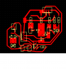
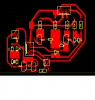
how many per pc board (3?)
trying to cut down on the number of terminal blocks needed.
they could add up

Just one detect per board. Signalling is on seperate board. I'm ok for connectors, they work out at 49p per board. Definately not as much as buying the board. With all parts each signalling board works out at about 90p, detectors will be less.

I may just use wires soldered, to where the connections need to be made, instead of connectors.

This way I can use the detectors for other things, not just for signalling.
 
circuit board and schematic

just copy, print then take to a phgoto copy machine and print on glossy photo paper.
iron onto CLEAN copper board.
etch then drill
 

Attachments

  • twnt mod pcb.PNG
    twnt mod pcb.PNG
    32.9 KB · Views: 130
  • twn t mod sche.PNG
    twn t mod sche.PNG
    32.9 KB · Views: 144
I put a bridge rectifier instead of separate diodes.
probally take less space if I did the separate diodes.

Mr Deb,

Just had a thought. I use only two back to back power diodes across my twin-t circuit instead of a 4 diode bridge rectifier. Can you try that on your simulator? The reason? Well Angie cannot 'up' her DCC voltage and is stuck with 16 Volts. Using a bridge rectifier 'steals' 1.4 volts. My Twin-T works fine with two power diodes. The 0.7 volt loss across the track is negligible. I looked at Angies track plan and there is a fair amount of track. So just a thought.

But in any case I am slowly modigying my Twin-Ts by removing the diodes totaly and installing two PNP power transistors (BD442s). the circuit works just as well. Also these transistors need no heat sink because under DCC they dont even get warm.
 
BD442 has a base current rating of 1A. Will they get 2A while operating or will this be unusual?
 
Last edited:
If R6 is a locomotive drawing 2A (value about 6 ohms) where does the current go?

How much current is 185um?
 
If R6 is a locomotive drawing 2A (value about 6 ohms) where does the current go?

How much current is 185um?

An N guage loco draws about 0.5A. As I have no idea how resistors will affect current I don't know what difference a 0.5A loco plus 10 wagons, with 5K resistors on one axle of each, will make.

TINA says the resistance is ok with 10 wagons. Not sure how to sim a 0.5A loco though.

Edit:
Just added a 0.5A 12V (6W) motor across with the resistors for 10 wagons and it works, in sim at least.
 
Last edited:
Angie cannot 'up' her DCC voltage and is stuck with 16 Volts. Using a bridge rectifier 'steals' 1.4 volts.

I know it might be basic, but my power supply is apparently 15V so voltage to track is input voltage - 0.5V, so should give 14.5V. A loco is 12V. Not sure if this helps or hinders this problem.
 
BD442 is PNP. It really doesn't matter in this circuit because one of them is being used normally and the other is using "reverse beta". NPN or PNP should work.
 
BD442 has a base current rating of 1A. Will they get 2A while operating or will this be unusual?

OOps!! I made a typo. Yes it's a BD442. The specs in the shop indicate that it's a 4A device. For DCC there is little heat dissipation so on my controller I have no problems.
 
the current draw is 185um

No, no. Connect a pair of power diodes, in parallel and back to bacK between T1s base (that is also T2s emitter) and ground. i.e take out the bridge and put in the diode pair. That way there is only one diode in the each half cycle's current path. This asures a max voltage of 0.7 volts (or maybe a bit less) across the PN junctions of each Twin-t transistor.
 
If R6 is a locomotive drawing 2A (value about 6 ohms) where does the current go?

How much current is 185um?

Mr Mneary,

The current for the engine passes from the the DCC booster, across the track through the engine, through a shorted bridge rectifier (two heavy duty diodes in series for each half DCC cycle) and back to the dcc Booster.

The diodes, when conducting, provide a maximum voltage of 0.7 volts each (1.4 volts total) across the two back to back base/emitter junctions of the Twin-T transistors. i.e Most of the engine+car current passes through the two power diodes, allowing signal transistors to be used for the detectors (Twin-T)
 
yo Railway Pete, draw me a picture of what you want.
You really should download TINA 7 not 8
its free and not a bad simprogram.
I use LT SPICE as well as TINA.
if both come up with same results then am pretty safe it will not creat magic smoke on building actual circuit. But then there's Murphys Law
 
hope ths is what you are wanting?

I changed the resistor to a 1 K
17ma current draw
updated pc board (I missed a connection
 

Attachments

  • pc board twnt.PNG
    pc board twnt.PNG
    32.1 KB · Views: 142
  • 2diodes.PNG
    2diodes.PNG
    67.9 KB · Views: 245
yo Railway Pete, draw me a picture of what you want.
You really should download TINA 7 not 8
its free and not a bad simprogram.
I use LT SPICE as well as TINA.
if both come up with same results then am pretty safe it will not creat magic smoke on building actual circuit. But then there's Murphys Law

OK, here is a diagramatic explanation. Just replace the brige rectifier (4 diodes with two 2 amp power diodes.
 

Attachments

  • Bridge equivalents.pdf
    62.4 KB · Views: 169
I changed the resistor to a 1 K
17ma current draw
updated pc board (I missed a connection

Just to check.

1/ Which resistor are you talking about? Is it the one across the track? Is that the maximum value that the circuit allows before the Twin-T drop out?
I suggest you start with an 8 ohm resistor (at 2 amps DCC track current) and increase its value until the Twin -T drop s out. That should be the resistance across the axles of Angie's cars.

2/ Your PC card is nice but the high current carrying foils (Track current)should be much wider (3x would be OK).

3/ The LED in the common collector of the Twin-T should have a resistor of about 1K in series with it. (or is that the resistor you are talking about?)

Hm.
 
Not sure if it's the same for MrDEB but when I remove two of the diodes I get an error.

Angie,

I'd like to know what kind of error. Pls make sure that the diodes are back to back. If not then all of the DCC current will be diverted through a signal transistors PN junction during one half AC cycle of the DCC booster's output. Smoke!. A short should not cause an error. The circuit just won't work.
Please check to see if you have created an open circuit during half of a DCC AC cycle.

Also I sent a diagramatic explanation to MrDEb. You can check that out too.

If you just took out two diodes from the PC board diagram and have not replaced them with a jumper All the DCC power will try and go through the little teeny Twin-T transistors.
 

Attachments

  • Bridge equivalents.pdf
    62.4 KB · Views: 141
Last edited:
Mr Mneary,

The current for the engine passes from the the DCC booster, across the track through the engine, through a shorted bridge rectifier (two heavy duty diodes in series for each half DCC cycle) and back to the dcc Booster.

The diodes, when conducting, provide a maximum voltage of 0.7 volts each (1.4 volts total) across the two back to back base/emitter junctions of the Twin-T transistors. i.e Most of the engine+car current passes through the two power diodes, allowing signal transistors to be used for the detectors (Twin-T)
The signal transistors will receive 1.4V on their bases, which will force a lot more than a token current into the base. With one diode drop, the problem is less serious, but it depends heavily on the Vbe and base resistance of the transistor. A base resistor of a few hundred ohms would do no harm and would improve transistor life dramatically.
 
Status
Not open for further replies.

Latest threads

New Articles From Microcontroller Tips

Back
Top