Continue to Site

Welcome to our site!

Electro Tech is an online community (with over 170,000 members) who enjoy talking about and building electronic circuits, projects and gadgets. To participate you need to register. Registration is free. Click here to register now.

  • Welcome to our site! Electro Tech is an online community (with over 170,000 members) who enjoy talking about and building electronic circuits, projects and gadgets. To participate you need to register. Registration is free. Click here to register now.

3 aspect model RR signalling help plse

Status
Not open for further replies.
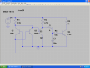
QUESTION on the Twin - T

the parts are very vague on type of transistors etc.
don't even mention NPN or PNP
on the schematic it shows -18 to -24 volts
is this a dual polarity supply??
need better schematic as it really isn't the beat for a novice such as Angie
part numbers would help.
 
missing something?

current direction dosn't seem right?
not deciphering something, gots o be something very simple but I sure as heck don't see it??
tried different transistors etc??
 
Schematic

Mr Deb

Aha! OK It's between -18 and -24 volts as Vcc. I originally used -18 volts because I had an old cheapy throttle aux at hand and used the AC aux output as a power source. After rectifying and smoothing it I got 18 volts. I had PNP transistors at hand so Vcc had to be negative. Hence -18 volts. After a while I got a hold of a fine 24 volt supply and used that. The Twin-T circuits and the signal controllers still worked. So using the components shown the circuit will work between 18 and 24 volts with VCC negative.

The transistors for T3 and T4 are 2N3906s from Radio Shack. I use old signal diodes scrounged from old PC cards. They carry so little current that they all seem to work. 1N914s are just fine and Radio Shack stocks them too.

Power transistors can be any PNP defice that can carry the max current of the DCC booster. (2 to 4 amps). Just ask the Radio Shack guys for a 2 or 4 amp power transistor in a TO220 package. (three pins, square tower with a hole in the middle for a heat sink if needed). The guys at Radio Shack understand all that stuff and can help Angie. I went to my eastern European equivalent and asked for a 4 Amp power transistor and drew him a diagram of the TO220 Package type. He threw two of something or other at me and it worked. That's what is nice about the circuit. Next time I go I'll ask him for the part number and pass it on. I hope all this helps.
 
current direction dosn't seem right?
not deciphering something, gots o be something very simple but I sure as heck don't see it??
tried different transistors etc??

If you are talking about the twin_T circuit the DCC current passes through the emitter/base junctions of both T1 and T2. T1 on the positive cycle and T2 on the negative. Is that the current path you are talking about?

When curent passes through one of the two transistors the common collector to which they are both strapped plummets to ground (0 volts). T3 will turn off. This will raise its collector to Vcc. Through R2, R3 and R4 (and C1) T4 will turn on (conduct) supplying current to the relay.

If you are talking about the diode matrix then consider that at 18 volts one needs a 1.5Kohm current limiting resistor. The LED being a diode drops about 2 volts. That means the resistor has to drop the other 16 volts. !.5Kohms at 16 volts is just over 10 Miliamps.

The LED cathode is at Vcc (-18volts). If one applies Vcc (-18 volts) at the junction between the LED and its current limiting resistor then both the anode and cathode of the LED are at the same voltage. (One has just shorted the LED out) The LED goes out. BUT the whole brunt of Vcc is now accross the resistor which now has 18volts across it and must now conduct a whole 12 milli amps instead of only 10. Instead of switching current on and off across an LED and its resistor one is merely diverting it through or around it.

Note that current is always flowing through R5. The green LED cathode is permanently connected to Vcc (-18 v)

So the matrix in its qiescent state indicates green. Should an approach be received, D5 supplies -18 volts to the Yellow LED circuit turning the yellow LED on. It also supplies -18 volts to D3 which turns the green off. Should the block be occupied, no matter what the signal is indicating, the -18 volts turns the red LED on and the green and yellow off via D2 and D4.

Also think about this. For a two aspect signal (green and red) one would not need D3, D4, D5, R7 and the yellow LED. One is left with two resistors, Two LEDs and a diode.

Does that help?

Pete
 
ah yes the power supply is AC not DC.
no wonder the simulation won't work.
I just want to simulate the circuit, not actually build it.
BUT using the correct voltage source would help.
will tray a square wave ac voltage,
 
AngieTemp01.jpg

AngieTemp02.jpg

Let's see if I did this right.... The elementary is the circuit I use on production boards. It has provisions for multiple logic inputs from detection. The jumpers are shown strapped for Twin-T current sensing. Optional detection methods may be deleted from the drawing when they are not used. Take careful note of the edge connector symbols as they separate the circuit from the world.

The circuit is over-engineered because the open collector outputs permit interfacing with many different logic families, as well as driving LEDs, Lamps, and relays for signal outputs. I have other circuits that operate as slaves from this master.

The connection diagram is derived from the "beta" site I use to test concepts. He has both DCC(DigiTrax) and Analog(DC) running concurrently. Each block is selectable. Only one rail need be gapped for signals. The power rail is gapped for control purposes. These are the drawings referenced in the PDF instructions on my site.

This circuit may be more complex than you want. The important issue is the flexibility and simplicity of the Twin-T detection. Four diodes and twn NPN tarnsistors. If this would be useful, let me know, I'll forward high resolution foil patterns.
 
The circuit is over-engineered because the open collector outputs permit interfacing with many different logic families, as well as driving LEDs, Lamps, and relays for signal outputs. I have other circuits that operate as slaves from this master.

.........Only one rail need be gapped for signals. The power rail is gapped for control purposes. These are the drawings referenced in the PDF instructions on my site.

This circuit may be more complex than you want. The important issue is the flexibility and simplicity of the Twin-T detection. Four diodes and twn NPN tarnsistors. If this would be useful, let me know, I'll forward high resolution foil patterns.

I'm only using DCC, and in theory all I need is the block detectors to light LED's, either signalling or control panel indicators. As you say only one rail is being gapped as I have no need for isolated sections and even if I did I could use a switch in the dcc power line for that particular block.

I think, going back to the detector basics, all that I need is a way to light an led when the block is occupied as an opto isolator/coupler is just an led which controls a transistor.
 
i AM PERPLEXED AS TO WHY?

RYING TO SIMULATE THIS TWIN T BUT NOTHING HAS YET TO WORK
USING ac FOR POWER BUT STILL won't work. Oups that caps lok)
I must be doing something wrong.
If using DCC then could the Twin Tee or what ever onree is using, just use DC (its own power supply) with its own seperate ground but connect to the rails.
perhaps cause to much noise for the DCC or ??
am totally lost in Idaho
 

Attachments

  • twin tee.PNG
    twin tee.PNG
    61.7 KB · Views: 161
I must be doing something wrong.

If using DCC then could the Twin Tee or what ever onree is using, just use DC (its own power supply) with its own seperate ground but connect to the rails.

I got the same in TINA, won't function. I'm using the components as noted on the schematic but relay doesn't work for some reason.
 

Attachments

  • BLOCK DETECTOR v4.JPG
    BLOCK DETECTOR v4.JPG
    34.3 KB · Views: 163
You like TINA . Pretty good program for some circuits.
LT SPICE is another good program.
going to try circuit but making some changes.
get back to you.
 
I understand TINA and can click on the switches to mimic the circuit. Thats good for me as I can see what happens.

I just checked out the site wherte my original idea for detection was. There's another one there which I've put into TINA and it sort of works. Not sure how to mimic AC power tho'.
 

Attachments

  • BLOCK DETECTOR v5.JPG
    BLOCK DETECTOR v5.JPG
    41 KB · Views: 174
I got the same in TINA, won't function. I'm using the components as noted on the schematic but relay doesn't work for some reason.

MrDeb,

The twin-T transistors that you are using for your simulation program are Darlington Pairs. I don't really know what their characteristics are. But they should be just two "bipolars". i.e. Emitter, base, collector. Secondly there is no load anywhere in the track (DCC) circuit. The Darlington pairs are humping the DCC output's maximum current. I smell smoke.

Get rid of the Darlington pairs and substitute power amplifiers. Then insert a resistive load from between 1k to 8 ohms after the Power supply switch and the Twin T transistors. When that works increase the load resistance to 10K and on up until the circuit stop working.
 
Twin Tee

Hi Guys,

I seem to remember something from years back. If I was in England I had to draw diodes backwards to the US protocol. Your simulation programs may not take this into account. Try and remove the relay diode from the circuit. If the relay latches then reverse the diode and reinsert. try again. the problem could just be the software.

Angie -- Where is the track in your diagram. I've never tried Darlington pairs in the twin t circuit transistors. Call up Radio Shack and ask them what they have as power "TRANSISTORS". I don't have my books here so I can't help. It's frustrating. I can't remember the nomenclature of the ones I used at ome.

Try this too. replace the twin t darlingtons with 2N3906s and insert a load of 2Kohms in series with the DCC power supply (after the switch). the relay should latch, and the 2N3906 wont burn up because of the high resistance across the track (Which you forgot to insert in the circuit)
 
Am not using a darlington pair.
using 2n3906's also tried several other type of transistors.
tried a 1 k resistor across the track rails etc.
going to sim the circuit Angi found
 
yes it looks like it works

double click on your voltage source then signal editor then wave type, amplitude etc.
curious, how did you get the diodes at 45degrees? angles??
 

Attachments

  • train5.PNG
    train5.PNG
    43.2 KB · Views: 163
RYING TO SIMULATE THIS TWIN T BUT NOTHING HAS YET TO WORK
USING ac FOR POWER BUT STILL won't work. Oups that caps lok)
I must be doing something wrong.
If using DCC then could the Twin Tee or what ever onree is using, just use DC (its own power supply) with its own seperate ground but connect to the rails.
perhaps cause to much noise for the DCC or ??
am totally lost in Idaho

MrDeb,

The circuit shown in this last message should work fine with a DC power supply. ( The TWIN-T has its own ) The DCC booster is connected (with a load in series with it ) across the two inputs at the lower left and across the twin t transistors.

The diagram I sent you has two sources of power. One for the twin-t circuit(s)
marked -18 to -24 volts, the other is marked DCC and implies the booster. I'll see if I can make the diagrams clearer and pass them on.
 
Mr Deb, Angie,

Attached more detailed info.

1/ Have customized circuit for Angie's requirements.

2/ Have attached also the current flow diagrams of both the positive and negative cycles of the DCC power booster.


NOTE to Angie. Your simplified circuit that 'works' on the simulator will actually work fine for only a short while. Both LEDs will be on at the same time for about two milli seconds before they blow. Hah! Why? I hear you cry. The diode rectifier provides an open circuit to the power supply. ALL of the high voltage will be across the LED circuit. Please put a jumper across the output of the rectifier. That will assure only 1.4volts for the LED circuit which is the intention of the bridge rectifier.

Once the circuit is working properly the LEDs will be flickerig at about 9Kilohertz. Does that matter to you? or do you want directional indications as well? The circuit will also not detect rolling stock occupying an unpowered section of track.

Also, be aware that your 16 volt DCC will drop to about14.4 volts. I think you can adjust your DCC output up to about 18 volts. That should do it OK.

Regards

pete
 

Attachments

  • Twin-T explained.pdf
    155 KB · Views: 197
Last edited:
Re: Twin-T and darlingtons

The circuit I posted was designed with 2N4401's. Hfe on the order of 100. Also have used 3904's, 2222's, a few others over the years.

Darlingtons have extraordinary gain compared to bipolars. But there is some loss of speed. I had a couple of applications where I used MPS-A27 darlingtons. They work well enough to drive a relay. They didn't work reliably driving the logic transistors. Base-Emitter voltage is higher than a bi-polar.

The second drawing(installation) shows a Twin-T detector as a stand alone simply to excite a "Previous" input to a module. Far left side of the drawing.
If the two collectors are separated, each can drive an LED with independant pull-up resistor. Thus providing directional indication. The rest of the circuit is display logic.

I do concede the complete circuit is somewhat over-engineered for what you desire. By studying the entire circuit, one can pull out that portion that is useful and ignore the rest. The Twin-T can actually be implemented with only one transistor and a pull up load. Relay, lamp, or LED and resistor.

It would be directional, of course, as the transistor would only conduct on one polarity. With DCC, one transistor might even work bi-directionally, since the supply is an A-C waveform. That's a "what-if" theoretical idea I may have to pursue.....

All of this has given me an idea worth pursuing. I have been obsessed with signalling both directions and providing interfacing to other modules. Just how far down can I strip this circuit and still get a usable signal? Thank you all....
 
Please put a jumper across the output of the rectifier. That will assure only 1.4volts for the LED circuit which is the intention of the bridge rectifier.

There already is a jumper across the rectifier's output. It's the horizontal line in the middle of it.

Once the circuit is working properly the LEDs will be flickerig at about 9Kilohertz. Does that matter to you? or do you want directional indications as well? The circuit will also not detect rolling stock occupying an unpowered section of track.

Directional is not relevant.

The led will be replaced by a photocoupler **broken link removed**

I thought a resistor across the axle of wagons would make the circuit so te led/photocoupler would be tripped. Is this not correct?

Also, be aware that your 16 volt DCC will drop to about14.4 volts. I think you can adjust your DCC output up to about 18 volts. That should do it OK.

My DCC has no option to increase output. I assume from this that if there are 4 blocks per power supply/booster each will drop the voltage, or is it only 1.6v per block, starting with 16v on each block?
 
Status
Not open for further replies.

Latest threads

Back
Top