Continue to Site

Welcome to our site!

Electro Tech is an online community (with over 170,000 members) who enjoy talking about and building electronic circuits, projects and gadgets. To participate you need to register. Registration is free. Click here to register now.

  • Welcome to our site! Electro Tech is an online community (with over 170,000 members) who enjoy talking about and building electronic circuits, projects and gadgets. To participate you need to register. Registration is free. Click here to register now.

3 aspect model RR signalling help plse

Status
Not open for further replies.
what is this signal driver?
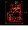
the board I posted has the detection circuit and the 3 led signal circuit.
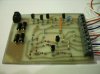
the strip board idea is a lot simpler than the design I posted. I like the simplicity for ease of construction. Never tried the press and peel but have seen posts using and the pros and cons of using..
I understand that Pulsar is selling their product in the UK at a reasonable price.
I could have made the board design smaller but Angi is a newbi at this so I used wide traces. Looking at your strip board design, it might be easier for her but ??
what software are you using to create the layouts you posted?

I use a student's computer which has AutoCad on it. It forces mr to learn Slovak too.
 
Dear All,

This is terrible. I can't find a way to change my password. Also the "remember me" tick in the check box does not work.

Can somebody inadmin help here. I need exact instructions

Thanks
 
Pete

Go to the menu option at the top 'UserCP'

Then click on the 'Edit Email & Password' option

Enter your current password where asked

Enter the new password you want in the 'New Password' and 'Confirm New Password' boxes

Click the 'Save Changes' button
 
Pete

Go to the menu option at the top 'UserCP'

Then click on the 'Edit Email & Password' option

Enter your current password where asked


Thanks Angie,

I think the site is making some changes. It seems to remember me now.

Any thoughts about a PC board design. MrDeb's board is fine. I don't know the measurements but if its small enough then I suggest you use it as a standard for your system. If you don't need a signal controler then just omit those components. As for size I tend to match the size of a PC board to the space availible. It makes the whole project maintainable. There is usually a lot of room under a layout so it makes no sense miniaturizing equipment. I use 4.5 inch square boards and I'm glad I made that decision because as my system's capabilities have expanded I had enough spare PC real estate to add and move things around. It's also nice to not have to use tweezers to remove components when experimenting.

What I sent you is what we in the industry call a 'lashup'. Before we put a design in concrete we use a hacksaw to make a PC board by cutting straight lines into the copper foil. Well after everything worked it was too much trouble to redesign a board so we just etched the lashup. Plan on maintainability and accessability.

Thanks for your help with my password.

Pete
 
some Christmas candy

here is the twin T with signals on same 3 x 4 inch board.
NOTE I saw mention of having two seperate boards, well MERRY CHRISTMAS
here is a board that has a cut line and marked jumpers for having the two boards seperate
will Email the file.
 

Attachments

  • twn t cutaway.PNG
    twn t cutaway.PNG
    31.8 KB · Views: 235
Thanks Guys

Thanks both of you. I've been trying to get my head around PCB design using various applications. I found one that autoroutes and you can then manually route after if not totally happy. Still in experimentation with that tho' :D

Will now set to building a 'final' prototype and see what happens. I've added a couple of connectors to my design as aux detectors. These can then be connected to things like auto level crossing barriers and turnouts etc.

Gotta say this is very impressive, actually building something for pennies which costs a fortune in the shops, and it doesn't have to connect to dcc controller.

Thanks again. Will let you know how I get on once I've built one.

Good luck Angie andrmember there are those of us who are modellers and there are those who like to plug and play.
Happy New year.
Pete
 
a word about auto routers = they sound good but not always the best IMO.
I myself like express pcb. easy to use, draw schematics etc.
hope you can use the design I sent you??
 
a word about auto routers = they sound good but not always the best IMO.
I myself like express pcb. easy to use, draw schematics etc.
hope you can use the design I sent you??

Hi MrDEB

Thanks for giving me the support you did on this.

Ended up with a new more spread out design with the connectors on each end (track one end, the rest the other end). The prototype is built and works just fine. Initially had detect on all time but it seems the flux I use is very conductive and needs to be cleaned off after soldering is done.

I did end up using PCB Express as the auto router I found worked fine if I had been able to find a laser printer to use, but as I used a pen to do the tracks the lines were too close to other components to allow for them to be drawn. Maybe I'll use it in the future tho' :)
 

Attachments

  • DetectorFinal.jpg
    DetectorFinal.jpg
    82.8 KB · Views: 249
Hi Pete,

As I said to MrDEB, thanks for all the support on this. The prototype works and now I can bulk order. Took a couple of days to get it sorted what with other things going on here but now it's done I feel great :D

Will contact you by email re the signal build, talk through a couple of ideas I have. But the detector/signal circuit works just right.
 
Status
Not open for further replies.

Latest threads

Back
Top