I'd like to know what kind of error. Pls make sure that the diodes are back to back. If not then all of the DCC current will be diverted through a signal transistors PN junction during one half AC cycle of the DCC booster's output.
It doesn't work, unless I'm missing something.
Also I sent a diagramatic explanation to MrDEb. You can check that out too.
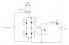
I checked out your pdf. And I did some searching on the web on rectifier circuits. I can't find one that uses only two diodes, they all use 4 unless it's connected to a trasformer.
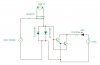
If you just took out two diodes from the PC board diagram and have not replaced them with a jumper All the DCC power will try and go through the little teeny Twin-T transistors.
Not sure where you want a jumper when there's only two diodes, maybe this is what I'm missing?
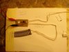
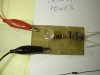
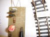
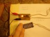
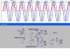
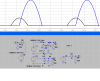
Attachments: Working.jpg (4 diodes) and NotWorking.jpg (2 diodes)
")