Continue to Site

Welcome to our site!

Electro Tech is an online community (with over 170,000 members) who enjoy talking about and building electronic circuits, projects and gadgets. To participate you need to register. Registration is free. Click here to register now.

  • Welcome to our site! Electro Tech is an online community (with over 170,000 members) who enjoy talking about and building electronic circuits, projects and gadgets. To participate you need to register. Registration is free. Click here to register now.

Yet Another ICD2 Emulator

Status
Not open for further replies.
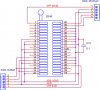
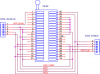
A MAX232 or FT232 based serial or usb ICD2 is really only objectionably slow when used in "debug" mode. My Serial ICD2, pictured earlier in this thread, uses dual regulators and probably cost about $10. I've only used it as a straight programmer with an adapter and have not had occasion to use it for ICSP or in "debug" mode.

Have fun. Regards, Mike
 

Attachments

  • PIC Programming Sockets.JPG
    PIC Programming Sockets.JPG
    44.2 KB · Views: 2,107
  • PPP- dsPIC adapter.JPG
    PPP- dsPIC adapter.JPG
    64.8 KB · Views: 490
Another PCB of ICD2USB by wonbinbk

This is the USBICD2 PCB. I used PDIP (through hole) PIC. So anyone who can not solder TQFP PIC can make this ICD2.
Firm-ware not changed.
 
Well here's the "flippy socket" for ICD2 clones. On 28-40 pin PICs the PIC is inserted with pin1 in the socket pin 1. On 8-20 pin PICs you turn the socket 180degrees and pin1 on the PIC goes into pin 21 (or 1R on the schematic)
 

Attachments

  • flippy socket.png
    flippy socket.png
    22.3 KB · Views: 467
William At MyBlueRoom said:
Well here's the "flippy socket" for ICD2 clones. On 28-40 pin PICs the PIC is inserted with pin1 in the socket pin 1. On 8-20 pin PICs you turn the socket 180degrees and pin1 on the PIC goes into pin 21 (or 1R on the schematic)

Happen to have PCB layout of it. I will be getting ICD2 clone soon. :)
I can draw it, but if you already have it.
 
Bill,

Looks similar to an adapter board I posted last October in this thread. My design allows for the use of a ZIF-40 socket or less expensive 20-pin single-in-line machined sockets. While the silk screen says "8-18", a newer layout says "8-20" (same electrical layout).

zif-40a-jpg.6190


One potential problem I see is that you're routing the PGC and PGD signals to multiple pins if a 40 pin device is installed. You've got seperate 8-20 and 28-40 connectors -- use 'em.

Regards, Mike
 
Last edited:
heh heh.. Thanks Mike, guess what this Mike will be etching in the garage this weekend. Will go look at the thread as I need just the tracks, or will photoshop the yellow out.

The single row of berg pins for the different PICS types? What are they for? I did not get a datasheet out. Easier to ask. Debug or something.
 
until now i cant find any solution to replace the microchip icd2.
i try many home made devices but all are too slow when use usb
 
The ICD2 serial devices can be slow in debug mode, keep the number of watch windows to a minimum will help. The only fast ICD2 clone seems to be a USB ICD2 that uses both a PIC16F877 and a PIC18F4550. This is a more costly and complex device.
If you want slow use a PicStart Plus
 
Status
Not open for further replies.

Latest threads

New Articles From Microcontroller Tips

Back
Top