Continue to Site

Welcome to our site!

Electro Tech is an online community (with over 170,000 members) who enjoy talking about and building electronic circuits, projects and gadgets. To participate you need to register. Registration is free. Click here to register now.

  • Welcome to our site! Electro Tech is an online community (with over 170,000 members) who enjoy talking about and building electronic circuits, projects and gadgets. To participate you need to register. Registration is free. Click here to register now.

Wind energy to electric energy

Status
Not open for further replies.
:lol: Thats some good engineering there...
 
i finally combined my data collection program with the output screen you see here..can you say PC storage scope.!!
the output you see here is from my generator connected through a diode bridge , through a 1 ohm resistor to a light bulb .. so essentially it is a current wave, whose magnitude is proportional to the current through the light bulb..
i havnt scaled it yet , i am thinking of putting all the data on another screen, have not decided yet..anyway it looks cool , i think ..

parts list :

MCP3004 A/D converter w/ SPI serial interface.
my PC I/O board , schematic available here
Pascal programming language

priliminary specs:
60 uSec / conversion
20 uSec calculations
80 uSec total convertion time , thats 12,500 convertions / sec.. lol its an old machine running dos and pascal :roll:
the 3004 is capable of 200,000 convertions/sec
 

Attachments

  • current_wave.jpg
    current_wave.jpg
    11.4 KB · Views: 1,212
the plan is to use another channel of the ADC to scroll the data back and forth , with a varible resistor..i have allready scrolled the data in one direction .. but then i have to stop the program and change the sign of my scroll value, to get it to go the other way..i should use a new procedure to get my scroll value..
the plan is to get it to move in the positive direction with values of 512 to 1023.. increasing in speed the higher the value..
and to move in the negetive direction from 511 to 0 increasing in speed the LOWER the value..i'm not sure how i'm going to do that yet.. :roll:
oh i've also got to set boundries , to prevent scrolling past the end of the array..
 
well i have done some experimenting with the generator again..mostly playing around with the PC storage scope .. anyway this is why i made it , because i needed a way to see which armature wasnt as good as the rest, and to find out why..
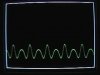
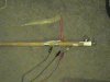
the first pic shows that the main peaks alternate every two ,thats when two magnets are over one armature at the same time..
That peak in the center of the first pic , has a little dip in it..i should be able to fix that..but i have'nt identified which armature it is yet
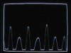
The blank spot in the second pic is where i shorted out one armature.. whats interresting about that pic is the peak that is supposed to be to the left of the blank spot , isnt much of a peak, i know which armature that is, its the only one of eight that was wound with thicker wire , ie less turns per same cross section area..and given that my wind generator may never see the speed that the propeller wind generators see , i may have to replace that one ..
needless to say i got the program and the ADC working satisfactorally although if anyone knows Pascal and is familiar with graphics viewports i could use some help with that ..
oh the wind speed indicator is doing well , it has been very windy tonight and it is spinning like .. well ..really fast..
 

Attachments

  • generator_output_3.jpg
    generator_output_3.jpg
    14.6 KB · Views: 1,140
  • generator_output_2.jpg
    generator_output_2.jpg
    12.9 KB · Views: 1,136
  • generator_output_1.jpg
    generator_output_1.jpg
    13.7 KB · Views: 1,136
i forgot to mention that , the way i was able to see each individual armature was , i took all the magnets off of the rotor except two..
otherwise all the peaks would all be similiar..
 
Eh WillB,
hello mate, eh that wind anemeter that you posted some time ago really interests me as my place is so hilly I want to find the best possie for a wind generator. do ya reckon you could post a schematic of it for me please so I can build one and give it a whirl so to speak. By the way your work on the wind turbine stuff has me reading for hours and it's great to see this post keeping on going and when I can finally get started this post should be the biggest this forum has seen.

Cheers Bryan1 :D
 
sure , i'll see what i can come up with..you mean the hall effect switch part? or the whole thing..?
 
Hi WilliB,
Yea mate the whole thing. I've just finished a 3 month shutdown working 12 hour days and my minds still a bit ..... well after a few ales.
Anyways I've got my lathe and mill up and working so now I can start to make a few things and get the ball rolling.

Cheers Bryan1 :D
 
O'kies the lathe is an old classic it's a flat bed but it aint been used for over 50 years, it's an old toolroom lathe 4' betwwen centres with a screw cutting gearbox and the mill is a Hardinge bridgeport which is a vertical mill with a 48" bed. And the best part is I used to own a machineshop and I still have all the machining tools and a box full of truck bearings suitable for wind genny's.

P.S. If ya onlinw Willi PM me so we can 'ave a yak :D
 
ok ..the first step in making a good wsd (wind speed detector) is the bearing. I started with a cheapo radio shack motor pic3..and attached the armature to a 3/4" dia stick.. then i attached the nylon bearing (pic1) to the can..
 

Attachments

  • 1_27_2005_9_37_pm_0002.jpg
    1_27_2005_9_37_pm_0002.jpg
    28.2 KB · Views: 1,101
  • 1_27_2005_9_20_pm_0002.jpg
    1_27_2005_9_20_pm_0002.jpg
    20.9 KB · Views: 1,097
  • 1_27_2005_9_37_pm_02.jpg
    1_27_2005_9_37_pm_02.jpg
    20.2 KB · Views: 1,095
pic3 is the bearing hot glued to the center of the can..
then i attached three tuna cans to the center can with small sheet metal screws as in pic2..
in pic1 i attached a cone to the back of each can..
pic2 also shows the center hole inside the can..and three HDD magnets for balance and to trip the hall effect sensor..
 

Attachments

  • 1_27_2005_9_04_pm_0002.jpg
    1_27_2005_9_04_pm_0002.jpg
    15.6 KB · Views: 1,084
  • 1_27_2005_9_04_pm_0005.jpg
    1_27_2005_9_04_pm_0005.jpg
    21.4 KB · Views: 1,088
  • 1_27_2005_9_04_pm_0001.jpg
    1_27_2005_9_04_pm_0001.jpg
    21.2 KB · Views: 1,080
Pic1 is the hall effect switch which i got from a PC power supply fan..
thats it at the top, with the three prongs comming out of it ..
the three solder connections at the bottom right of pic1 , are where the fan windings connect to the circuit board..this is the output of the circuit..The middle one has a normally high output and goes low when a magnet passes close enough to it..
If you connect the red wire to 5V , the black wire to ground ,the output is 0 to 5 V ..
 

Attachments

  • 1_27_2005_9_20_pm_0007.jpg
    1_27_2005_9_20_pm_0007.jpg
    12 KB · Views: 1,095
  • 1_27_2005_9_14_pm_0001.jpg
    1_27_2005_9_14_pm_0001.jpg
    25 KB · Views: 1,082
  • hall_sensor_178.jpg
    hall_sensor_178.jpg
    16.7 KB · Views: 1,080
instead of a tuna can anemometer i have made a tuna head anemometer .. taking the shape from the very hydrodynamic tuna ..
it works very well.. it even has ball bearings so the slightest whisper of a breeze starts it moving..
Next i have to figure how to count the JUST the tranitions of the hall effect switch..as it is now i am able to count the number of times it is IN transition.. i am sure it is just an if then statement
 

Attachments

  • th_202.jpg
    th_202.jpg
    18 KB · Views: 1,023
Eh WilliB,
I found an interesting site www.thebackshed.com thats the bloke that did the article for that Fisher/paykel steppermotor for a wind genny, anyway he's got another design using a simple steppermotor for charging nicads. I made one today based on the saviuonas design but as usual there isn't any wind :x . I reckon this is a top site for people to use those old steppers to good use to take a look mate I'm sure ya'll be impressed.

Cheers Bryan1 :D
 
Bryan , you gotta post some pics of your savonius..
Last night i wound another armature with 22 gauge wire (0.025 " diameter) ,it had a resistance of 1ohm so i calculated that it was about 60 feet ..
anyway with a test fixture which is a motorcycle brake rotor 12" dia. spinning at 300 RPM , and two magnets , i just got 7 V p-p . no load..
the wave has a similar shape to the one a couple pages back .. just bigger..
 
i was thinking about the difference between the pull on the armature ,when i have the armature connected through a diode bridge , and when it isnt..
both tests were done with a 1ohm resistor as load..as you might guess the pull was considerably higher without the diodes in place..why you might ask? the answer is the forward Voltage drop on the diodes..so i googled ultra low forward voltage drop and this came up..
https://www.electro-tech-online.com/custompdfs/2005/02/PMEG1020EA_1.pdf
at 2 Amps these diodes have a forward voltage drop of only 460 mV !! wow..!! they have a 5 Amp version in the works
here
https://www.electro-tech-online.com/custompdfs/2005/02/mbrs320.pdf
is another one.. with 0.36 forward voltage drop at 3 A .. wow..
 
Hiya peoples,
Well I finally got round to making a wind genny, my saviounis version needs a total rethink to the design but the one pictured looks promising. I used a bipolar stepper motor rated @ 5 volts and draws 1amp. Well the initial tests show a voltage of 12.6 volts with a current of about 250 milliamps using a 5watt 1 ohm resistor as the load. Now thats when the prop is doing approx 50 rpm. Murphy's law states when you make a wind genny you wont get any decent wind. Good ol' murphy woz right again :oops:
Anyway the last pic is of the retifying circuit using 2 wo4 bridges and a 47uf cap, I shrunk some heatshrink over the board once it was wired up and shoved the lot in the back of the soupcan which is sealed using silastic. The prop was made from some scrap water pipe and I need to take it off and balance it.

Cheers Bryan1 :D
 

Attachments

  • circuitboard1.jpg
    circuitboard1.jpg
    172.4 KB · Views: 1,626
  • windgenny1.jpg
    windgenny1.jpg
    137.1 KB · Views: 1,619
  • windgenny2.jpg
    windgenny2.jpg
    157.3 KB · Views: 1,623
nice !!
i was thinking about the Fisher/Paykil site .. He used the same magnets that came with the machine ? ..i suppose that if he had used some of the new Neodium (sp) magnets , he could get more power out of it..
50 RPMs is plenty to work with , with some more work on the prop i bet you could get it to 200 RPMs !!
 
Status
Not open for further replies.

Latest threads

New Articles From Microcontroller Tips

Back
Top