daviddoria
New Member
I will post a drawing later, but for now lets see if my description works.
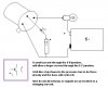
The idea is when you push the button on circuit A, the LED on circuit B turns on.
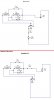
Circuit A
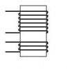
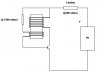
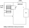
A battery is connected to a momentary switch that turns the whole thing on when it is pressed. The switch then is connected to the base of an NPN transistor through a current limiting resistor. The collector is connected to the (+) battery terminal. The emitter is connected to a LC circuit (parallel) that controls the wave frequency.... still wondering what to do with the (-)...
Circuit B
The exact same LC circuit as in circuit A is used as the first stage of circuit B. The output of the LC is connected to the base of an NPN transistor. The collector is connected to a new battery (as the circuits will be separated). The emitter is connected to an LED through a current limiting resistor. The negative of the LED is connected to (-) battery.
will that work?
The idea is when you push the button on circuit A, the LED on circuit B turns on.
Circuit A
A battery is connected to a momentary switch that turns the whole thing on when it is pressed. The switch then is connected to the base of an NPN transistor through a current limiting resistor. The collector is connected to the (+) battery terminal. The emitter is connected to a LC circuit (parallel) that controls the wave frequency.... still wondering what to do with the (-)...
Circuit B
The exact same LC circuit as in circuit A is used as the first stage of circuit B. The output of the LC is connected to the base of an NPN transistor. The collector is connected to a new battery (as the circuits will be separated). The emitter is connected to an LED through a current limiting resistor. The negative of the LED is connected to (-) battery.
will that work?
")