Continue to Site

Welcome to our site!

Electro Tech is an online community (with over 170,000 members) who enjoy talking about and building electronic circuits, projects and gadgets. To participate you need to register. Registration is free. Click here to register now.

  • Welcome to our site! Electro Tech is an online community (with over 170,000 members) who enjoy talking about and building electronic circuits, projects and gadgets. To participate you need to register. Registration is free. Click here to register now.

Why Opamp with potentiometer?

Status
Not open for further replies.
By changing 2 op amps and adding resistors I ran into a new problem. I 'm not able to see the voltage output of circuit completely at the transient analysis. Actually I apply 1V sin (with frequency of 1khz) to lower channel input while upper channel input is grounded. I am supposed to see a sinusoidal waveform at the very last output. But In analysis settings when I set RUN TO TIME= 1ms, I have errors like this one: Convergence problem in transient analysis at Time = 1.071E-06
After I change run to time or Tstop to 1us the voltage waveform isn't shown complete. I don't know how can I solve this problem. every single change in circuit creates new problems :(
 
I have mentioned about this in my post 34. That most op-amp simulation models (model statements) incorrectly model the power-supply current.
And this is why this circuit will never work in simulation program. In real life the circuit might work, but I would add emitter degeneration resistors into current mirror.

Here you can see the proof.
If I use LT1363 as a op amp LTspice gives the correct result. But if I change the op amp to TL072, I don't get correct result.


WOuld you please tell me In transient analysis why this circuit is simulated untill 1.1us and it doesn't go further while The Tstop is 2000us?! This kind of problem is also related to the model statements of op amps?

Thanks in advance
 
By changing op amps of current mirrors to LM358 and adding (250 ohm) resistors to emitters of transistors, output of current mirrors works right. With 1Vdc on both channels I got 0.1v. by applying -1Vdc I got -0.097 v. At the output of buffers I got almost the same value.
But when upper channel is 0Vdc and lower is 1Vdc (between 10k resistors is still grounded ), Output of top buffer is 1.63mv and the lower buffer is 0.1v. Also, the last output is 0.99v.

That sounds right doesnt it? If you get a small offset like 1mv or so dont worry as that is part of the model of the LM358 showing the way the input offset works.

Since you have other problems now too since i last read this thread, is there any chance you can switch to LT spice? I think that will work better and i can follow your work step by step because i have that simulator too. We can start with the top section, get that working, then add the bottom section later, then add the output stage, once both sections work ok.
 
What's differnce between Orcad pspice and LT spice? I don't have LTspic software. first of all I have to install it on my pc. second of all I'm not familiar with working in LT spice area probably it takes time to become familiar with it if it's very different from Orcad pspice. As I solved problems related to DC sources and changed some parts. I ran into a new problem with simulation of this circuit in Transient state and Ac sources. If you think this circuit may work in real world I start assembling it on soldress breadboard. Besides if you think there is no difference between LTspice and Orcad pspice I try finding LTspice.
 
Hi,

Well from the problems you are having it seems that something is wrong beyond what we can know without seeing the actual simulator program in depth, but LT Spice is free and i might even be able to set up the circuit for you. In fact, i'll take a look at that this morning and see if i can set the circuit set up at least the upper stage, and see how it works in LT Spice. If it works, then i would strongly suggest downloading the free LT Spice and using the file i'll post here later.
I am not sure what op amp models they have but they should have something appropriate.
Check back in a couple hours.

BTW if you can use that simulator program you would probably find that LT Spice is simple. If you really dont want to download then i'll see if i can get the whole thing simulated.

How hard would it be for you to breadboard say the upper section and test that in real life, do you have a solderless breadboard handy?
 
I would be grateful if You try simulating this circuit in LT spice. Untill now I can't download a correct exe of Ltspice. a few weeks ago I assembled the upper stage of this circuit without buffer on breadboard but AS I said in many posts ago I had oscillation (2Mhz) when I tried to change offset voltage to 0v. In fact I was even confronted with worse problem in real life. So due to occuring this kind of problem I decided to simulate the whole circuit in pspice at first, and see if I get the appropriate gain I put it on breadboard. By the way I keep trying to find a correct link
for downloading LTspice.
 
Last edited:
Hello again,

I'll see if i can find a link for you.
In the mean time, here's a simulation of the upper section of the circuit using LT Spice.
As you can see, the output is nearly the same as the input with equal resistors (2k).

Oh, so the oscillation only occurs with 0.000v input? Well guess what. Once the current mirrors are added, this circuit is no longer a perfectly linear circuit like most op amp circuits, but becomes partly digital in nature. That's because when the input signal goes through zero the current mirror mostly responsible for the output current switches from the upper mirror to the bottom mirror or vice versa. Adding a resistor from the positive supply terminal to the negative supply terminal of the op amp may help this situation because then both current mirrors are always working to some degree, more so than without the extra resistor to draw more quiescent current. The problem may not show up in a simulator.

As another note, i had to use the LM358 in this simulation because the LT model for the first op amp i tried DID NOT draw any current through the power supply pins! None at all, so that illustrates clearly that not all models are suitable for simulation of this kind of circuit. The LM358 model seems to work fine though, and you can see the 1 ohm resistors used i the power pins to sense current just to check to make sure it works right.

Here's a link for the LTSpice:
https://www.linear.com/designtools/software/?gclid=CO3Ims3PxL4CFQNqOgodQTkASQ#LTspice
 

Attachments

  • AmplifierWithCurrentMirrors-9.gif
    AmplifierWithCurrentMirrors-9.gif
    45.7 KB · Views: 144
Last edited:
As another note, i had to use the LM358 in this simulation because the LT model for the first op amp i tried DID NOT draw any current through the power supply pins! None at all, so that illustrates clearly that not all models are suitable for simulation of this kind of circuit. The LM358 model seems to work fine though, and you can see the 1 ohm resistors used i the power pins to sense current just to check to make sure it works right.

Where is LM358? I can't find it in opamps. All of them are LT model.
 
Hi,

Those resistors are just for testing, the R4 R5 R6 just for getting a known voltage into the op amp for testing, the 1k just left over from another experiment.

I am sorry, the model for the LM358 i will attach here. The file name should be LM358.mod and you must put it under the LT Spice subdirectory:
\lib\sub\


Note that if you download the attachment you must change the name to LM358.mod (this forum only allows certain file extensions so i changed it to LM358.txt before uploading).

Code:
*//////////////////////////////////////////////////////////////////////
* (C) National Semiconductor, Inc.
* Models developed and under copyright by:
* National Semiconductor, Inc.

*/////////////////////////////////////////////////////////////////////
* Legal Notice: This material is intended for free software support.
* The file may be copied, and distributed; however, reselling the
*  material is illegal

*////////////////////////////////////////////////////////////////////
* For ordering or technical information on these models, contact:
* National Semiconductor's Customer Response Center
*  7:00 A.M.--7:00 P.M.  U.S. Central Time
*  (800) 272-9959
* For Applications support, contact the Internet address:
*  amps-apps@galaxy.nsc.com

*//////////////////////////////////////////////////////////
*LM358 DUAL OPERATIONAL AMPLIFIER MACRO-MODEL
*//////////////////////////////////////////////////////////
*
* connections:
*   non-inverting input 1
*   inverting input 2
*   positive power supply 3
*   negative power supply 4
*   output 5
*
.SUBCKT LM358  1  2  3  4  5
*
*Features:
*Eliminates need for dual supplies
*Large DC voltage gain =  100dB
*High bandwidth =  1MHz
*Low input offset voltage =  2mV
*Wide supply range =  +-1.5V to +-16V
*
*NOTE: Model is for single device only and simulated
*  supply current is 1/2 of total device current.
*  Output crossover distortion with dual supplies
*  is not modeled.
*
****************INPUT STAGE**************
*
IOS 2 1 5N
*^Input offset current
R1 1 33 500K
R2 33 2 500K
I1 3 44 100U
R3 55 4 517
R4 6 4 517
Q1 55 2 44 QX
Q2 6 7 44 QX
*Fp2=1.2 MHz
C4 55 6 128.27P
*
***********COMMON MODE EFFECT***********
*
I2 3 4 75U
*^Quiescent supply current
EOS 7 1 POLY(1) 16 49 2E-3 1
*Input offset voltage.^
R8 3 49 60K
R9 49 4 60K
*
*********OUTPUT VOLTAGE LIMITING********
V2 3 8 1.63
D1 9 8 DX
D2 10 9 DX
V3 10 4 .635
*
**************SECOND STAGE**************
*
EH 3 98 3 49 1
G1 98 9 POLY(1) 55 6 0 9.8772E-4 0 .3459
*Fp1=7.86 Hz
R5 98 9 101.2433MEG
C3 98 9 200P
*
***************POLE STAGE***************
*
*Fp=2 MHz
G3 98 15 9 49 1E-6
R12 98 15 1MEG
C5 98 15 7.9577E-14
*
*********COMMON-MODE ZERO STAGE*********
*
*Fpcm=10 KHz
G4 98 16 33 49 5.6234E-8
L2 98 17 15.9M
R13 17 16 1K
*
**************OUTPUT STAGE**************
*
F6 4 3 POLY(1) V6 300U 1
E1 3 23 3 15 1
R16 24 23 17.5
D5 26 24 DX
V6 26 22 .63V
R17 23 25 17.5
D6 25 27 DX
V7 22 27 .63V
V5 22 21 0.27V
D4 21 15 DX
V4 20 22 0.27V
D3 15 20 DX
L3 22 5 500P
RL3 22 5 100K
*
***************MODELS USED**************
*
.MODEL DX D(IS=1E-15)
.MODEL QX PNP(BF=1.111E3)
*
.ENDS
*
 

Attachments

  • LM358.txt
    2.9 KB · Views: 165
Last edited:
OK It's done. I got the same result as yours. Now do I add the lower stage? before adding the lower one I think I should make some changes. shouldn't I? Actually in previous file you applied some changes to upper stage like applying 15v to non inverting pin of op amp. I have to turn all of them back to what i had.
 
Last edited:
Hi again,

Yes you should be able to add the lower stage, and yes get them to look the same as your original schematic. I used some of those resistors just for testing to make sure it worked right.

I looked for oscillation and could not get it to oscillate.
 
I draw the whole circuit and got the result which is shown in Untitled1 , I hope this time The very last output has a correct result. How can I increase the value of gain? If I multiply gain of first stage and second stage I get the TOTAL gain. I know the gain of last stage but what is the gain of first stage ( From inputs untill buffers)? Actually I want to change something in this circuit to increase the value of gain. It seems this circuit acts like a buffer, dosen't it?
 

Attachments

  • Untitled1.png
    Untitled1.png
    74.9 KB · Views: 154
  • Untitled.png
    Untitled.png
    83.4 KB · Views: 137
Last edited:
Hello again,

There are a couple ways to change the gain.

Part 1:
If you look at the first stage of each section, you see a gain of 1 buffer. You know how that works. If you input 1v you get 1v out. If you input 2v you get 2v out, etc.

Part 2:
Next, there are the two 10k resistors on the output of the input buffers. With 1v in (and 1v out) we get 1/10000 amps through the 10k With 2v in we get 2/10000 amps through the 10k.

Part 3:
Next, that current goes through the input of one of the current mirrors (upper or lower depending on polarity). The current mirrors act as current controlled current sources with a gain of 1. So for 1ma through the op amp power pin we get 1m out of the current mirror.
With 1v on the input we get 1/10000 amp through the input of the current mirror and so we get 1/10000 amp at the output of the current mirror. Thus the voltage-to-current gain from input to the output of the current mirror is 1/10000.

Part 4:
We have a 1k resistor on the output of each current mirror. With 1ma through 1k we see 1v across that 1k. With 1v in we get 1/10000 amp out so we only see 0.1v across the 1k, so the voltage gain from input to the output of the current mirror is 1/10.

Part 5:
The output stage is a differential amplifier with a gain of 10. For 0.1v input (difference) we get 1v output. Thus the input voltage to output voltage gain of the whole circuit is 1.

To increase the gain there are a couple different things to try.

First, decreasing the 10k resistors on the output of the two input buffers would increase the input voltage to buffere output current ratio so that would mean more current through the input of the current mirrors PER volt of input. Decreasing them to 1k would mean a ten fold increase in current, so that would increase the overall gain by a factor of 10.

Second, the 1k resistor at the output of each current mirror converts the current back to a voltage. If we increase the 1k to a higher value the output voltage will be higher for the same amount of current. Thus raising the 1k to 10k would cause a gain increase by a factor of 10 also.

Third, the output amp gain can be increased by decreasing the two 10k resistors. Deceasing them to 1k would cause a gain increase of 10 again.

Doing all three of these things would increase the gain by a factor of 1000, at least theoretically. You'd have to investigate the best method here. For example, raising the gain of the output stage means imposing more of a limit on the upper frequency range for the circuit.

Also note Part 2 is a little more tricky when one of the inputs is zero because then the zero input still gets a signal from the other section but it gets inverted. We could write an equation to solve for any input though.
 
There are a couple ways to change the gain.

Part 1:
If you look at the first stage of each section, you see a gain of 1 buffer. You know how that works. If you input 1v you get 1v out. If you input 2v you get 2v out, etc.
What do you mean by the first stage? you mean opamps and the current mirrors connected to them? why do they have the unity gain? I thought each of op amp with current mirrors and 1k resistor on the output of them has the gain of 0.1.

Part 2:
Next, there are the two 10k resistors on the output of the input buffers. With 1v in (and 1v out) we get 1/10000 amps through the 10k With 2v in we get 2/10000 amps through the 10k.

in this part I don't get what you said. :-(, why 1/10000 amps?
 
Last edited:
The first stage is either input buffer.

1 volt across 10k means it has 1/10000 amps flowing through it.
 
Doing all three of these things would increase the gain by a factor of 1000, at least theoretically. You'd have to investigate the best method here. For example, raising the gain of the output stage means imposing more of a limit on the upper frequency range for the circuit.

Thank you so much for your good explanation. I have one question.Why does raising the gain of output stage impose more limit on upper frequency? I hope in real life when I breadboard it I get this result, because op amps that I have are TL081. while in simulator I used LM358. I don't know why do you think LM358 is better than TL081? You said they have different model statement in LTspice because of that you choose LM358. but I want to know these differences
may affect the result that I'm supposed to get in real life or not?
 
Last edited:
All modern opamps reduce gain at high frequencies so that when negative feedback is added then the frequency where the phase-shift changes it to positive feedback then the gain is less than 1 so the opamp does not oscillate. It is done with one capacitor and is called, "frequency compensation".

The datasheet for all opamps shows a graph of the gain without feedback vs the frequency. For the TL081 the maximum gain is about 200,000 from DC to about 20Hz. At 100Hz the gain is about 40,000. At 1kHz the gain is about 4,000. At 10kHz the gain is about 400. At 100kHz the gain is about 40. At about 3MHz or 4MHz the gain is about 1. At higher frequencies the maximum gain is less than 1.

The LM358 has poor high frequency response because it uses low power supply current.

Additionally, the slew rate limits the highest frequency that the output can swing at a high level. for the TL081 its output can swing to 100kHz. For a lousy old 741 opamp its output can swing at full level up to only 9kHz (less than half the audio band). For an LM358 its output can swing at a lower level to only about 2kHz.
 
Thank you so much for your good explanation. I have one question.Why does raising the gain of output stage impose more limit on upper frequency? I hope in real life when I breadboard it I get this result, because op amps that I have are TL081. while in simulator I used LM358. I don't know why do you think LM358 is better than TL081? You said they have different model statement in LTspice because of that you choose LM358. but I want to know these differences
may affect the result that I'm supposed to get in real life or not?

Hi,

I did not say that the LM358 was better than the TL081, i merely meant that the *model* used would be better for this *simulation* because that model models the power supply pin currents better. We might find a better model for the TL081 which also shows this functionality. In the real life circuit i would expect the TL081 to work better in terms of the frequency response.

An increase in gain of the output stage is just one way that may decrease the frequency response of the overall circuit. As audioguru explained, when the gain of an op amp stage is increased the maximum frequency goes down proportionally, so if we increase the gain by a factor of 10 then we decrease the usable upper frequency by a factor of 10 too. So if we originally had a gain of 10 and 200kHz top response, after increasing the gain to 100 (10 fold) the top frequency would decrease to 20kHz approximately. That's the way most op amps work and is usually referred to as the "Gain Bandwidth Product" of the op amp. There is a little more to it than that (the slew rate also limits the upper usable frequency) but that's the first approximation to start with in understanding how this works.

What this means is that choosing another method to increase the gain might be better because it may not limit the usable frequency range as much. The transistors are much faster than the op amps, so increasing the current mirror current is probably a better method to increase overall gain. In fact, that may be one of the advantages of using current mirrors in the first place but you'll have to look into this more. If the output stage gain was set to 1 with an increase in gain somewhere else then we might actually see amplification by a factor of say 10 without impairing the frequency response very much. You'll have to try this because there is more involved than just setting the gain.
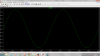
Thinking out loud, if the output slew rate is 1v/us then with a 10k output resistor on the first stage we get 100ua/us which leads to 100ua/us on the output and with a 10k on the output we see also 100ua/us which leads to 1v/us so the response did not improve.
If we decrease the buffer output resistor to 1k, we still see 1v/us but now we see 1ma/us, and so 1ma/us on the output and so with that same 10k output resistor we see 10v/us, so we've increased the slew rate.
This is all theory so far, there will be limits as to how far we can take this if in fact we did not overlook anything already.
 
Last edited:
Considering this circuit is a voltage amplifier, changing 10k resistors on the output of input buffers at the first stage to 1k may affect the input resistance(Rin ) of amplifier.
Actually this amplifier should have a high input resistance. So increasing 1k resistors at the output of current mirrors can be a good way for increasing the gain of whole
circuit.
As far as I know increasing the slew rate would be good for the greatest possible rate of voltage change. In fact when I have a fast slew rate, output can change state quickly to follow the input. But I'm not sure increasing the slew rate in this circuit would be a great idea. because when I change output resistors of input buffers to 1k. in one hand I
reduce input resistance. On the other hand I increase the slew rate. Actually I don't know so much about slew rate that's why I have a little doubt about reducing 10k resistors.
I would be grateful if You tell me I'm thinking right or not?
 
Status
Not open for further replies.

New Articles From Microcontroller Tips

Back
Top