Continue to Site

Welcome to our site!

Electro Tech is an online community (with over 170,000 members) who enjoy talking about and building electronic circuits, projects and gadgets. To participate you need to register. Registration is free. Click here to register now.

  • Welcome to our site! Electro Tech is an online community (with over 170,000 members) who enjoy talking about and building electronic circuits, projects and gadgets. To participate you need to register. Registration is free. Click here to register now.

Why Opamp with potentiometer?

Status
Not open for further replies.
Hi,

Where did you get that graph of the CMRR from for the 741 ?

The data sheets all say 70db min, so something else must be wrong. Did you null the amplifier before taking the readings? That op amp requires a 10k pot connected to the null terminals and the arm goes to the minus power supply (V-).

After nulling check again if you did not null it yet.
 
The graph was in datasheet attached to this post. No, I didn't connect any pot to the null terminals. I thought adding pot is necessary when I don't have a small offset. You mean the pot affects CMRR?
 

Attachments

  • ua741.pdf
    164.7 KB · Views: 200
Last edited:
Hi,

I have seen other data sheets that spec over 100db so 90db sounds reasonable, but there must be a reason for only measuring 45db so i thought you could try the null adjust because that probably helps to make both inputs respond more equally, which improves the CMRR.

How are you measuring the CMRR and how are you calculating it, and what kind of equipment are you using?
 
I used function/signal generator to input signal then selected 10hz and 100hz as the frequency of input signals. for both of them CMRR was about 45 db. At first I grounded the inverting terminal and inputted about 2v to non inverting terminal in fact I applied different voltages to the resistors that connected to op amp terminals then measured the output voltage and calculated differential gain.
for common mode gain I applied about 2v to both of 1k resistors at the input terminals then measured the output voltage with both voltmeter and oscilloscope and calculated CM gain. At the end I used the formula of 20 log(Ad/Acm) to get the CMRR.
I thought 45db would be a good result because I did test it in real world and this differenece with datasheet seemed reasonable to me.

I didn't measure the DC offset, not Once. SO If you think with the pot I may have another result for CMRR then I will do it.
 
Last edited:
This difference would be reasonable or not?
Were you making the measurements under the same conditions (i.e. ± supply voltages, input signal amplitude, resistor values) as specified in the datasheet? Are you comparing your measured CMRR against the minimum, typical, or maximum datasheet value?
 
I used function/signal generator to input signal then selected 10hz and 100hz as the frequency of input signals. for both of them CMRR was about 45 db. At first I grounded the inverting terminal and inputted about 2v to non inverting terminal in fact I applied different voltages to the resistors that connected to op amp terminals then measured the output voltage and calculated differential gain.
for common mode gain I applied about 2v to both of 1k resistors at the input terminals then measured the output voltage with both voltmeter and oscilloscope and calculated CM gain. At the end I used the formula of 20 log(Ad/Acm) to get the CMRR.
I thought 45db would be a good result because I did test it in real world and this differenece with datasheet seemed reasonable to me.

I didn't measure the DC offset, not Once. SO If you think with the pot I may have another result for CMRR then I will do it.

Hi,

The CMRR is dependent on imbalances in the input circuits, so nulling seems like a good idea. For God's sake it doesnt take much to try so why not try it? Just hook up a 10k pot that's all you need. Adjust for the best zero output you can get with zero differential DC input.
Later you can also adjust it a little to see if the CMRR changes too if you like, after you've nulled it and tested it that way first.

BTW this isnt on a solderless breadboard is it? That could make a difference too. Might as well try the pot first though.

It's on a solderless breadboard. ok, I will connect the pot to null terminals.
 
Were you making the measurements under the same conditions (i.e. ± supply voltages, input signal amplitude, resistor values) as specified in the datasheet? Are you comparing your measured CMRR against the minimum, typical, or maximum datasheet value?

Through the whole test I didn't change input signal amplitude, supply voltages and resistor values at all. Supply voltages were -15v and +15v. I have no idea about resistor values besides in datasheet that I have resistor values weren't specified. I compared the CMRR with the graph in datasheet. In datasheet
CMRR at 100hz was 90db. By the way I attached datasheet and configuration of circuit to this post.
 

Attachments

  • Untitled.png
    Untitled.png
    12.3 KB · Views: 163
  • ua741.pdf
    164.7 KB · Views: 168
I assembled the whole circuit (below picture) with 741 op amp on solderless breadboard to get the differential gain. I had a strange result. The output voltage of buffer (n005) was 0.5v while 1v was applied to non- inverting terminal input. I have a question This problem might be because of internal structure of 741 op amp or not?
 

Attachments

  • Untitled.png
    Untitled.png
    92.7 KB · Views: 181
Last edited:
Did you null the input offset?
 
Hi,

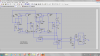
In the real life circuit we cant depend on the transistors in the current mirrors all being EXACTLY the same. There will be some imbalance. You could check this by using small resistors in series with the current mirror collectors. See how different they are with the real life circuit.

Im not sure if i still have IC's with multiple transistors inside or i would try this myself, at least to test the current mirrors without the rest of the circuit as that is my guess of what the problem could be right now. They may even have to be matched. It would be pointless to try this with separate transistors. The voltage/current characteristics have to be identical, and if the temperature changes the voltage/current characteristics have to change the same in both transistors, so we're asking a lot.

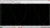
I am still intrigued by this circuit though (at least with one set of current mirrors) because it is able to increase the output slew rate, which is very important for the large signal response (and therefore the usability) of the op amp.

We could look into what to do about such an imbalance. Some sort of current mirror offset adjustment maybe, but there is a chance that using the offset null of the 741 might do it too. Depends on how much range you can get and if that is functionally a good enough approach to begin with.

The 741 inputs should be ok as long as they are within about 4 volts of either rail. So any input should be between say -11 and +11 volts with a plus and minus 15 volt supply.
The outputs should be within about 2v of each rail i think, and no greater.

For testing CMRR you have to use resistors less than 10k, but 1k resistors are the most common to use i think, so using 1k resistors should give good results.

Come to think of it i dont think i have any 741's around anymore either as i stopped getting them long, long, long, long time ago. I still get LM358's once in a while, and some specialized extremely low input offset types. Dont have to use them much anymore though except for the occasional measurement.
 
I use transistor arrays instead of discreet transistors and I thought when I use them, transistors in a array transistor are balanced at least more than discreet transistors.

I used potentiometer only for the last op amp at the last stage. I didn't null rest of op amps in my circuit separately.because I didn't know how to do it in a particular order. I think in a way that if I have offset in output voltage then I reduce it with potentiometer at the last stage. in general from the very beginning choosing a suitable op amp was one of my concerns. I think most of my problems mostly depend on the internal structure and construction of op amp.

Even though the voltage output of first buffer is 0.5v, The output voltage of both current mirrors are correct (0.1v). the very last voltage output is less than 0.1v instead of 1v. I checked all the connection 3 times all of them was correct. it's very interesting except the last stage all of voltages are almost good as I expected. the last stage works well when it is separated and not connected to the rest of circuit. After it's connected to the the buffers and current mirrors , dosen't work good and I have 0.1v which was the wrong result. before I build the whole circuit I assembled only half of the circuit which means I put one buffer at the input stage , one current mirror, a buffer next to it and the last stage. with this circuit I had the result as it had to be. In fact when I add extra components I run into this problem and don't have correct output voltage.
 
Last edited:
Hi,

Sounds strange, why is there an output of 0.5v at the output of the first buffer?
 
Is the current mirror providing enough current for the 741 to operate correctly? 'Typical' supply current is 1.7mA, max is 2.8mA.
 
Hi Alec,

How could it not? Isnt the power supply terminal connected through the transistor but the transistor itself is connected as a diode, right? So it's like having a diode in series with each power supply lead, correctly oriented of course to allow conduction. Take a look and see if that is right.
 
Yes, you're right MrAl. I should have checked the schematic again before posting :oops:.
 
I solved my problem with first buffer. With 1v input I got almost 1v from the very last output. So the whole circuit is working ok now.

I have another issue, In real life circuit when I change R4 and R5 to 10k and apply 1v to the non inverting terminal of op amp shown in the picture, The last output becomes saturated. In fact My objective is to get gain of 10 with the input of 1v. I didn't decrease input voltage to 0.1v. maybe if I did that, I would have a correct result.

In general I did this thing to increase the gain of circuit. I could increase the resistors in the last stage but it affected the gain bandwidth product. Now I don't know how to increase gain without saturating the last output.
 

Attachments

  • Untitled.png
    Untitled.png
    27.1 KB · Views: 180
Last edited:
Hi,

What do you get on the output with only 0.9v on the input?
In fact, what voltage can you go up to (0.5, 0.6, 0.7, 0.8, 0.9) before the output saturates?

I would not expect it to saturate because it's only 1v and a gain of 10 overall, which results in an output of 10 volts. You are talking peak voltage here i hope, because if you are talking RMS voltage then yes it will saturate because the peak of 10vrms is around 14.14 volts peak and that's too high for the 741 with plus and minus 15 volt supplies.
 
I mean when I apply SINE voltage with the peak of 1v to one of terminals. I expect to see a sine voltage with the peak of +10 and -10 at the screen of oscilloscope (like in the picture) but the output becomes saturated.
 

Attachments

  • Untitled1.png
    Untitled1.png
    83.8 KB · Views: 163
Hi,


Ok i just had to clear that up for obvious reasons. Now we know you are using 1v peak for sure, and expect 10v peak output.
However, you did not specify what input you CAN use without a problem. Is it 0.9, 0.8, 0.7v peak on the input or does it have to be even less than that?

That output should be obtainable, but how do you know it is saturating? Maybe the current mirrors can not handle it?
When you have a problem like this you have to go through each stage one by one and find out what stage is causing it.

From what we know about the 741 it can handle up to about +12v on the output with light load when the supply is +15v, and -12v with a -15v supply. In other words, plus and minus 12v output with plus and minus 15v supplies. So if this is not working then you have to check the 741 itself.

On a separate plug board, try testing the 741 to see that it can get up to 10v peak on the output with a gain of 10 and 1v peak on the input. It's easy enough to wire this up with a couple resistors. Test that and see what results you get. You might also test all the 741 packages you have to make sure they all work ok.
 
Status
Not open for further replies.

Latest threads

New Articles From Microcontroller Tips

Back
Top