Continue to Site

Welcome to our site!

Electro Tech is an online community (with over 170,000 members) who enjoy talking about and building electronic circuits, projects and gadgets. To participate you need to register. Registration is free. Click here to register now.

  • Welcome to our site! Electro Tech is an online community (with over 170,000 members) who enjoy talking about and building electronic circuits, projects and gadgets. To participate you need to register. Registration is free. Click here to register now.

What is the problem?

Status
Not open for further replies.

mindhacker

New Member
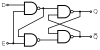
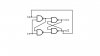
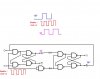
I am about to make a perfect D flip-flop out of simple gates. I used 74ls00 as illustrated in the diagram. It works perfectly alone but when i connect its input to a circuit it started to work incorrectly. Example is this. I connect its Q' to its D input. Q is supposed to be 0 then 1 then 0....but it works indefinitely. As if it is in undefined state What causes this? How can I fix it?
 

Attachments

  • 300px-D-Type_Transparent_Latch.svg.png
    300px-D-Type_Transparent_Latch.svg.png
    4 KB · Views: 182
  • d.JPG
    d.JPG
    12 KB · Views: 157
It sounds like a timing problem.

Look at the IC data sheet & calculate the delays of each path for each state and see if there are any timing races.
 
what should i do? e=clock and i am using a clock pulse generator that has diff frequency controlled by a potentiometer.
 
You can do one of two things:-

Do what I suggested in my previous post or,

Buy a D type Flip Flop.
 
there is some thing wrong in your connection, when Q' is low that is connected to D input, when E goes high imediately Q' comes high and D goes low, this has to be prevented.

Edit: you have to add another latch stage driven by inverted clock input to enable it and take the feed back from that output. see the attached pic
 

Attachments

  • delay latch.JPG
    delay latch.JPG
    21.5 KB · Views: 175
Last edited:
It is not working. When the clock is high Q and not Q' are both high. Maybe this means that the rs is in racing condition?
 
did you check the one i posted? in your circuit you are allowing both inputs to go high simultaniously by your feedback and its not allowed. you get 1 in both out put, you may be right, i beleive your latch is oscillating with high frequency.

you have to make an intermidiate latch as i suggested to hold the feed back until the clock goes high/low
 
The only problem with the original is that the input stage gets a clock to each gate, D input to one gate and D NOT to the other input. The out put of this section connects directly to the input of the RS section without any type of crossover.
 
D ff

This is the most straight forward version of a D Flip Flop I have encountered. The state of D is transferred to Q One clock transition later. Sorry about the quality of the drawing but I have to use Paint since I can’t load foreign programs onto my system.
 

Attachments

  • D-FF.GIF
    D-FF.GIF
    2 KB · Views: 216
This is the most straight forward version of a D Flip Flop I have encountered. The state of D is transferred to Q One clock transition later. Sorry about the quality of the drawing but I have to use Paint since I can’t load foreign programs onto my system.

you are right, this is the common way when your input is external and the input only changes when the clock is low. the OP needs to utilise the out put fed again to the input, that is where the problem is.
 
Connect Q NOT to D. the first half of the above is different than any of the other configurations above.
 
I have tried everything you said using 74ls00 but it doesnt work. grrr. but when im using the real D f/f ic which is the 74ls175 it works perfectly.
 
Then I guess it is time to pull the drawing of a 74LS175 and check out the difference in the two circuits. The one I posted was from the web and was the simplest form. There is another configuration that uses 7 gates total including one set up as an inverter that allows preload and reset. It uses 3-input NAND gates in most locations.
 
but its just symbol also.

hi,
It works in LTspice simulation, a low value capacitor has been added to stop the circuit from oscillating at start up.
 

Attachments

  • AAesp01.gif
    AAesp01.gif
    35.8 KB · Views: 194
Status
Not open for further replies.

Latest threads

Back
Top