Continue to Site

Welcome to our site!

Electro Tech is an online community (with over 170,000 members) who enjoy talking about and building electronic circuits, projects and gadgets. To participate you need to register. Registration is free. Click here to register now.

  • Welcome to our site! Electro Tech is an online community (with over 170,000 members) who enjoy talking about and building electronic circuits, projects and gadgets. To participate you need to register. Registration is free. Click here to register now.

Is there a difference?

shortbus=

Well-Known Member
Most Helpful Member
Never designed a circuit before but do know how to Google. Have tried to find my answers with no success, so here goes.

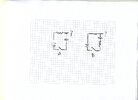
In the illustration is there a difference in the result on how the circuit is made? I'd like to keep the resistor out of the output path of the cap, or caps, since this will make up a cap bank where one or more are used at a time.

Second question. Where the question mark is on the out put of the drawings, does the output equal the amount of charge put in the cap or does it not have an out put until the cap is charged fully. The caps are of different values and I'll be sizing the resistors so they end up with a similar charge tim, so they can all discharge together.

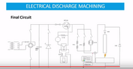
The caps/cap bank will be monitored by a comparator and when charged to a certain voltage level they then will get discharged into a spark gap. This is for an electrical discharge machine, a project that got me into studying electronics in the first place and a bucket list project. Thanks for any help in my understanding this.
 

Attachments

  • RC CR187.jpg
    RC CR187.jpg
    222.2 KB · Views: 113
"Normally" one assigns one node in circuit as ground, then the question
mark is a little clearer, if referring to voltage, it is the V with respect to ground.

1701540736310.png

Keeping R, as in A schematic, a good idea, since cap when discharging will
provide larger current and V (if output is taken across cap).


Regards, Dana.
 

Attachments

  • 1701540597923.png
    1701540597923.png
    461 bytes · Views: 85
Last edited:
Your diagrams more little sense, you can't just have one connection.

I'm sorry, but when I had the battery, I assumed the negative pole of it would suffice. That link is one of many I read, and it still didn't answer my second question, is there a voltage out of the circuit with respect to ground before the cap is fully, 5 time constants charged?
 
Keeping R, as in A schematic, a good idea, since cap when discharging will
provide larger current and V (if output is taken across cap).

That is my problem, I only want and need the charge stored in the cap, not the complete source voltage and amperage. Once the cap reaches a certain voltage a comparator will switch off a mosfet not shown, but shown as the battery.

The idea of the total circuit(not shown) is to make every discharge of the caps as similar as possible. In EDM that is the holy grail, a stable spark, not the way all of the home made machines do it in Youtube videos. I ran EDM machines for ~13 years at work and want to make mine as close to an industrial machine as possible.
 
I'm sorry, but when I had the battery, I assumed the negative pole of it would suffice. That link is one of many I read, and it still didn't answer my second question, is there a voltage out of the circuit with respect to ground before the cap is fully, 5 time constants charged?
If you don't show it, then we've no idea what you might be using - we 'could' assume you're using the negative of the battery, but we've no way of knowing if that's true - particularly with the slightly bizarre drawings.

The webpage I posted for you explains everything, complete with formulas - but obviously there will be a voltage during charging, there's no mechanism for there not to be.

Think of the capacitor as a bucket (bigger the bucket, the larger the capacitor) - and the resistor as a water pipe (larger the pipe, smaller the resistor) - as water flows out of the pipe the water level in the bucket rises, it's exactly the same for a capacitor.
 
Keeping R, as in A schematic, a good idea, since cap when discharging will

Thanks for the link! But your quote above doesn't match up with the Falstad circuit. The Falstad circuit shows the resistor after the cap like my drawing 'B' showed.

I wish the Falstad circuit had the switch in a different place, so I could see what is happening at the output/discharge while the cap is also charging.
 
Think of the capacitor as a bucket (bigger the bucket, the larger the capacitor) - and the resistor as a water pipe (larger the pipe, smaller the resistor) - as water flows out of the pipe the water level in the bucket rises, it's exactly the same for a capacitor.

I know my drawings were wrong. But I understand and comprehend the working of caps.
 
Thanks for the link! But your quote above doesn't match up with the Falstad circuit. The Falstad circuit shows the resistor after the cap like my drawing 'B' showed.

I wish the Falstad circuit had the switch in a different place, so I could see what is happening at the output/discharge while the cap is also charging.

Then use the Falstad simulator and design your own ....


Regards, Dana.
 
Rather than a Capacitor discharge EDM, I would use either an IGBT or BJT rated for HV and > 10A with lots of heatsink, low ESL or a low rep. rate like 1 Hz with 150Vdc 2.5A and I got 350 W arc pulses so not very efficient due to switch losses and crude current sensing.

All caps and inductors added are physical or parasitic properties of components attempted to be somewhat realistic.

My design attempted to model the 50 V breakdown threshold of the EDM tool which at ~1kV/mm may be a 5 thou or 0.05 mm gap. This was used to etch ceramic.

I used emitter current sense with gain using 100 mohm for 2.5A pulse 4us wide with 250W EDM power.
Inductance cannot be zero but with suitable cables so I chose a low value for ESL and Cp for the electrode capacitance.

The electrode properties for arc resistance and holding current were carefully selected. It is well know since Faraday's day that arc resistance is inversely proportional to the electrode surface area and current passed. I just optimized it for max power it might not be practical.

Falstad can plot power of each component if the sampling time is fast enough for impulses and slow enough sweep to capture at least one cycle for average power.

- anyone is welcome to offer suggestions for improvements or new requirements.

Researchgate article

1701725367090.png
 
Rather than a Capacitor discharge EDM, I would use either an IGBT or BJT rated for HV and > 10A

That''s how most of pulse EDM's shown on Youtube do it. But having used edm the sparks from the Youtube machines are nothing like ones from a real industrial machine. What I'm trying to make is what was used in my favorite machine to run,an Eltee Pulsetron. It didn't have on/off settings because it used the caps to control the frequency of the sparking. Select a small cap and you got faster smaller sparking like for finishing. A bigger cap value got you slower frequency higher amperage sparks for roughing.
My design attempted to model the 50 V breakdown threshold of the EDM tool which at ~1kV/mm may be a 5 thou or 0.05 mm gap

The overburn gap measurement in what we did was only 0.001 per side, so when making electrodes that is what we designed them for. This was for cores and cavities in plastic injection molds that made the connector bodies for GM car electrical systems.

I'll print out and study your links, thanks.
 
anyone is welcome to offer suggestions for improvements or new requirements.
https://tinyurl.com/yrb64fgz

OK, after looking quickly at the research gate paper, I see it's talking about Wire EDM, not sinker like I'm trying to make. Wire does use transistor type discharging, because the wire is moving so fast that it doesn't react like a sinker electrode. And that is why I couldn't find a spark gap in your Falstad circuit either. Though they both are called EDM they are really not too similar when it comes to the power supply/spark generator.

Trying to explain EDM to electronics people that have spent their life trying not to end up making sparks is hard, it doesn't tend to compute for them.:) Buy doing it is why I started trying to teach myself electronics at ~60 years old. Making the actual mechanical part of the machine was easy since I have been a die maker/machinist my whole adult life. The mechanical part was finished in the 1990's.
 
Last edited:
Falstad has an arc gap and I used it in my simulation. You must edit the specs. What arc threshold voltage and current do you want?

Making the electrode is not hard but defining/controlling the gap area for its electrical properties is the key. So I guess you start by copying existing ones. Also the capacitance of dielectric like water is 80x air.

Here's a DIY version on YT.

1701737604602.png


more info on web
 

Attachments

  • 1701737410690.png
    1701737410690.png
    127.7 KB · Views: 78
Last edited:
Are you building a high precision machine or just bulk metal removal?

I've worked on electromechanical machines for metal removal, "drilling" type effect?

Really not high precision but that comes from the electrode shape and size. The electromechanical drilling circuit is the basis of my design parameter. They use or the one we had used, pulsed cap discharge and they have a very similar spark size and amperage for each spark. That is what I'm after.
 

Latest threads

New Articles From Microcontroller Tips

Back
Top