Continue to Site

Welcome to our site!

Electro Tech is an online community (with over 170,000 members) who enjoy talking about and building electronic circuits, projects and gadgets. To participate you need to register. Registration is free. Click here to register now.

  • Welcome to our site! Electro Tech is an online community (with over 170,000 members) who enjoy talking about and building electronic circuits, projects and gadgets. To participate you need to register. Registration is free. Click here to register now.

Is there a difference?

shortbus=

Well-Known Member
Most Helpful Member
Never designed a circuit before but do know how to Google. Have tried to find my answers with no success, so here goes.

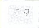
In the illustration is there a difference in the result on how the circuit is made? I'd like to keep the resistor out of the output path of the cap, or caps, since this will make up a cap bank where one or more are used at a time.

Second question. Where the question mark is on the out put of the drawings, does the output equal the amount of charge put in the cap or does it not have an out put until the cap is charged fully. The caps are of different values and I'll be sizing the resistors so they end up with a similar charge tim, so they can all discharge together.

The caps/cap bank will be monitored by a comparator and when charged to a certain voltage level they then will get discharged into a spark gap. This is for an electrical discharge machine, a project that got me into studying electronics in the first place and a bucket list project. Thanks for any help in my understanding this.
 

Attachments

  • RC CR187.jpg
    RC CR187.jpg
    222.2 KB · Views: 113
What arc threshold voltage and current do you want?

Making the electrode is not hard but defining/controlling the gap area for its electrical properties is the key. So I guess you start by copying existing ones. Also the capacitance of dielectric like water is 80x air.

Here's a DIY version on YT.

My transformer will give after rectifying and a large cap have an open circuit voltage of ~98VDC, and then a bulk resistor will take the ~20A down to 15A. The transformer is a used one from a servo drive and I can't find any specs on it, the company went out of business. So then the cutting/burning voltage is the in the 50VDC -20VDC range after the ~98VDC ionizes the oils dielectric. Those are the parameters most all industrial machines use.

When you say water as a dielectric your talking about wire EDM. Sinkers use oil. When the company bought 3 new Charmilles CNC sinkers the front office said we had to use deionized water like the wire machines. But a wire has very little debris from the cut, where the sinker has much debris, When the company that supplied the deionizer tanks started charging big bucks to clean and replace the deionizing medium they soon let us go back to using oil.

The circuit you got from Youtube is similar to the ones most all of the youtubers are using. Basically just switching a high amperage DC on and off with a PWM circuit. If you look at those guy's machines when they are burning you see very large sparks, but then if you look at Reliable and another good Youtube channel, "learn to burn" their sparks are much smaller and more controlled.

Another reason for most of Youtube's doing what they are doing spark wise is because of their ram drive/motors. most are using a small DC gearmotor and a fine thread lead screw. So in essence they have little to know control of the gap. So they make the spark generator more powerful instead of controlling the ram advance better. You can get more control with a stepper motor and a coarse thread, and use micro stepping control. With that setup you can make each move of the motor 0.001 which is the preferred gap distance. Then you work on getting the sparks more under control.

If you read in the PDF you posted on page 140 last sentence in the first paragraph, they say it all when it comes to sinker EDM, paraphrasing, "controlled sparks" is the key. Using the circuit you posted there is no real control of the spark, it's either off or on at full voltage.

EDM is slow work, so while the machine was burning the job I was reading all of the manuals for the machines we had. And trying to understand the process better, I bought a couple of text books on EDM by people who taught it in college, then started to try to learn electronics. I know what a machine should do but am having a hard time putting it into getting the electronics to work.
 
Last edited:
The electromechanical ones I worked on (mostly used for removing broken taps) used the same principal as a buzzer; a coil in the cutting head in line with the electrode, that pulled the electrode holder away from the job against a spring.

There was also a big series inductor the power unit, so each time the arc stopped and the electrode dropped back against the workpiece, the short circuit current would ramp up and start to lift the electrode away, which re-struck the arc, then the inductors would help maintain it for some time.
 
The Tap Buster or Tap Disintegrator units use a similar means but are quite different in design, i.e. very low voltage - high current AC. the operating head is often constructed by feeding a coil with 60hz AC to set up the vibratory method.
Quite crude in comparison to true EDM.
 
They used 3 resistor switches for 7 levels of current limit plus off using binary 1R, 2R, 4R limiters, where the R values may be series or parallel to share dissipation in the same power rating.
1701816461053.png


Sparks generate hydrogen in oil which can slowly evaporate, but if it exceeds the LEL of 4% then it becomes explosive.

The Oil filled transformer industry knows this well and use dissolved gas analysis DGA to sample H2 content. Higher energy corona can generate higher thresholds of explosive gasses from MEthane to Acetylene. So controlled dissolved gas content is a key item.

I don't know how commercial EDM's control the electrode height or pressure and thus arc threshold voltage. Excitation voltage in clean transformer oil can be 25 to 75 kV/mm but significantly reduced with dissolved gasses and oil contaminants, which affects arc threshold voltages and explosive risks. Testing these thresholds might be a useful way to measure DGA contamination by reducing the voltage charged on the caps using triac controlled primary DC but demands much higher heatsinks on the Triacs or a slow ramp up. 25 kV/mm means 25 V/um which may be translated into electrode pressure for arc voltage. My guess is they don't care about excitation voltage as long as the gap is small enough with pressure and control the current with resistors. Thus the big spark is reduced this way then jog to break the current when switched off but still hot to raise the holding current and prevent electrode stiction. Thus fresh oil filtered and pumped is key to minimize oil contamination.

As you can tell I have not had your experience, so my assumptions could be wrong.

Other unrelated info.

I once considered designing a C60 8 port ignition system with nuclear grade graphite in inert gas vacuum to convert graphite into the extremely $$$/gm valued C60. A friend who also helped invent DLC coating for metals in Ukraine had a $1m/y contact for making the C60 to improve bearing lifetimes significantly in grease but lacking specs for the electrode pressure with stepper control and energy pulse, we decided not to invest time and money into the project. I was to do the electronics and another had all the CNC tooling. C60 aka bucky-ball carbon looks like a soccer ball and makes grease roll like soccer balls with extreme elasticity. He made samples but this had to be scaled to tonnes per year. But now that RU has commandeered the UKE nuclear reactors, we would now have no source for this grade of graphite.

DLC= diamond like carbon coating makes aluminum or steel increases immunity to scratches.
 
Last edited:
I don't know how commercial EDM's control the electrode height or pressure and thus arc threshold voltage. Excitation voltage in clean transformer oil can be 25 to 75 kV/mm but significantly reduced with dissolved gasses and oil contaminants, which affects arc threshold voltages and explosive risks. Testing these thresholds might be a useful way to measure DGA contamination by reducing the voltage charged on the caps using triac controlled primary DC but demands much higher heatsinks on the Triacs or a slow ramp up. 25 kV/mm means 25 V/um which may be translated into electrode pressure for arc voltage.

Originally they used simple voltage comparators to make a window comparator circuit. When the voltage was high the ram went down and when too low it goes up. The machines of today use a mcu of some kind to do that. The original rams were hydraulic and used something called a piddle valve to make very small changes in the ram cylinder position.

Their seems to be a problem using Triacs to control the spark discharge, they can't be turned off until the voltage goes too l for the spark gap. Maybe a GTO type would work though.

If you want to read about EDM the first book I bought is available now on PDF I bought mine new before the made a PDF, very expensive and used ones are still expensive. here is the link - https://archive.org/details/jameson...hiningsocietyofmanufacturingengineersmachinin
 

Latest threads

New Articles From Microcontroller Tips

Back
Top