Continue to Site

Welcome to our site!

Electro Tech is an online community (with over 170,000 members) who enjoy talking about and building electronic circuits, projects and gadgets. To participate you need to register. Registration is free. Click here to register now.

  • Welcome to our site! Electro Tech is an online community (with over 170,000 members) who enjoy talking about and building electronic circuits, projects and gadgets. To participate you need to register. Registration is free. Click here to register now.

Water Activated Alarm

Status
Not open for further replies.

ElectroMaster

Administrator
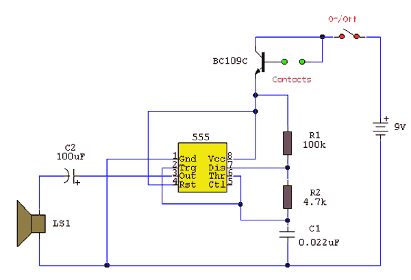
The circuit uses a 555 timer wired as an astable oscillator and powered by the emitter current of the BC109C. Under dry conditions, the transistor will have no bias current and be fully off. However as the probes get wet the transistor will conduct and sounding the alarm.

An On/Off switch is provided and remember to use a non-reactive metal for the probe contacts. Gold or silver plated contacts from an old relay may be used, however a cheap alternative is to wire alternate copper strips from a piece of veroboard. These will eventually oxidize over but as very little current is flowing in the base circuit, the higher impedance caused by oxidization is not important. No base resistor is necessary as the transistor is in emitter follower, current limit being the impedance at the emitter (the oscillator circuit).
water_activated_alarm.gif
 
I bulit this circuit on electronic workbench...but this is not working....plz have a look at it and tell me where i went wrong.
 

Attachments

  • untitled_272.gif
    untitled_272.gif
    4.4 KB · Views: 3,109
What's the changeover switch for?, that wasn't on the original circuit!.

You need to add a resistor between base and collector of the transistor, to simulate the resistance of the water.
 
I found this circuit diagram for the same water activate alarm in other site...Every compononets are similar but the one capacitor from node 5 is missing in the above circuit...Have a look...which one works????
 

Attachments

  • 4_708.gif
    4_708.gif
    5.8 KB · Views: 3,250
wolverin said:
I found this circuit diagram for the same water activate alarm in other site...Every compononets are similar but the one capacitor from node 5 is missing in the above circuit...Have a look...which one works????

Either should work.
 
Can somebody plz send me a working schematic circuit of this one on EWB file plz.....i am so dumb tht i cud not make either of this work.

But i'm really intrested to do this one as my project.
 
The 1st circuit will work if you wire the transistor as shown in the original schematic and use a speaker instead of a buzzer.

The 2nd circuit will work if you wire all parts like in the schematic.
 
wolverin said:
I bulit this circuit on electronic workbench...but this is not working....plz have a look at it and tell me where i went wrong.

Is it just me, or is everyone noticing that the ground symbol is connected to nothing :?:

Connect ground to the -ve terminal on the battery.
 
You have no sensor contacts on the base of your transistor. In your version, you are simply switching +9volts from collector to base. The contacts (green dots in the original) when activated by moisture, supply the small current necessary to allow the larger current to flow through the collector-emitter circuit of the transistor. This then provides the Vcc to turn on the 555 timer and allow it to oscillate. :roll:
 
hmmm....would there be a way to modify the sensortivity of the water sensors?, so it only works when the sensors are a certain amount of wetness?
 
rancid rock said:
hmmm....would there be a way to modify the sensortivity of the water sensors?, so it only works when the sensors are a certain amount of wetness?
Change the 10k resistor to 100k, the 56k resistor to 560k and the 0.01uF capacitor to 0.001uF. Then it will be 10 times more sensitive.
Change the 10k resistor to 1k, the 56k resistor to 5.6k and the capacitor to 0.1uF. Then it will be 10 times less sensitive.

You could also add something conductive to the water like salt or something. Or use distilled water that conducts nearly nothing.
 
I would suggest using carbon electrodes so as to avoid corrosion and oxydation: aluminium creates a nice insulating layer when it oxydizes and this layer may prevent the alarm from working and it's the same for almost any metal (excluding gold but it's a bit expensive ;)).

Carbon electrodes can be taken from graphite pencils (sorry english is not my native language and I don't know the simple words ;)).

uski
 
Hello

I didn't understand the part of contacts
how it will be and how it will work if the water touchs it ??!!!
 
cannibal said:
I didn't understand the part of contacts
how it will be and how it will work if the water touchs it ??!!!
Water has some salts in it then it is conductive.
When water is between the contacts in the first circuit then it turns on the transistor that turns on the oscillator.
 
Can i insert a photocell in this cct to prevent it triggering when rain falls during the night when i am in bed and if so where in the cct should it be best placed without effecting the operation too much.
 
Status
Not open for further replies.

Latest threads

New Articles From Microcontroller Tips

Back
Top