The 555 timer is capable of producing accurate timing ranges from microseconds to hours and therefore has many practical uses for every level of electronics. It is an especially good integrated circuit for electronic hobbyists to learn with. I will guide you through the basics and will also show you an example circuit.
Some features:
- Operates on a range of supply voltages
- Timing from micro seconds to hours.
- Monostable and astable operation
- Adjustable duty cycle
- High output current (upto 200mA)
- High Temperature stability
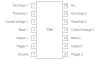
Pin Configuration
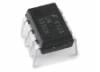
The 555 is available in an 8-pin dual-in-line package or in a circular TO-99 metal can with eight leads.
There is also a dual timer, which is basically two 555's in a single package, it is contained in a 14-pin dual-in-line package. The 556 shares the power pins.
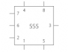
In a schematic, the 555 symbol will look similar to this:
Operating Modes
The 555 has three operating modes: Astable - producing a square wave, Monostable - producing a single pulse when triggered, Bistable - a simple memory which can be set and reset. Each mode works differently and is explained below
Astable
In astable mode, the 555 timer puts out a continuous stream of rectangular pulses. These pulses have a specified frequency which is controlled by the values of two resistors, R1 and R2 and by the timing capacitor, C1.
The timing of the pulses can be worked out by:
T1 = 0.693 (R1 + R2) × C1
T2 = 0.693 (R2) × C1
T = 0.693 (R1 + 2R2) × C1
T2 = 0.693 (R2) × C1
T = 0.693 (R1 + 2R2) × C1
Before calculating a frequency, you should know that it is usual to make R1=1 kΩ because this helps to give the output pulses a duty cycle close to 50%, that is, the HIGH and LOW times of the pulses are approximately equal.
Monostable
In the monostable mode, the 555 timer acts as a “one-shot” pulse generator. The pulse begins when the 555 timer receives a signal at the trigger input that falls below a third of the voltage supply. The width of the output pulse is determined by the time it takes to charge the capacitor C1 to 2/3 of the supply voltage. The output pulse width can be lengthened or shortened to the need of the specific application by adjusting the values of R1 and C1.
The output pulse is called the Timer Period (T) and can be calculated by:
T = 1.1 × R1 × C1
Bistable
The 555 timer can also run as a bistable flip-flop meaning the output is stable until either the trigger or reset inputs are pulled low.
If the Trigger is pulled low (1/3 Vcc) by pressing the button in the circuit then the Output goes HIGH.
If the Reset is pulled low (> 0.7v) by pressing the button in the circuit then the Output goes LOW.
Specifications
These specifications apply to the NE555. Other 555 timers can have different specifications depending on the grade (military, medical, etc).
- Supply voltage (VCC): 4.5 to 15 V
- Supply current (VCC = +5 V): 3 to 6 mA
- Supply current (VCC = +15 V): 10 to 15 mA
- Output current (maximum): 200 mA
- Maximum Power dissipation: 600 mW
- Power Consumption (minimum operating): 30 mW@5V, 225 mW@15V
- Operating temperature: 0 to 70 °C
The links below allow you to download documents in Adobe Acrobat ©, PDF, format. In the unlikely event that you don't already have Acrobat Reader, you can download the latest version direct from Adobe:
Download the full datasheet in PDF format:
NE555 Datasheet
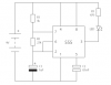
Example Circuit: Flashing LED