Continue to Site

Welcome to our site!

Electro Tech is an online community (with over 170,000 members) who enjoy talking about and building electronic circuits, projects and gadgets. To participate you need to register. Registration is free. Click here to register now.

  • Welcome to our site! Electro Tech is an online community (with over 170,000 members) who enjoy talking about and building electronic circuits, projects and gadgets. To participate you need to register. Registration is free. Click here to register now.

Water Activated Alarm

Status
Not open for further replies.
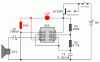
i made a automatic dam door control system using 555 timer but after that ...... i tought 0f using microcontroller and i did it ..... insted of all this u can only do by switch which will activate on any conduction ....... r ugetting me ..... this circuit is only for the understanding of transisters
 
xl5 said:
Can i insert a photocell in this cct to prevent it triggering when rain falls during the night when i am in bed and if so where in the cct should it be best placed without effecting the operation too much.
I added an LDR (light dependent resistor) and a 100k resistor. When it is light then the LDR is a low resistance and the 555 operates normally. When it is dark then the LDR is a high resistance and the 100k resistor causes the 555 to be reset. Try different values for the 100k resistor.

This way, the battery is drained about 5ma when the sensor is wet in the dark. If the sensor is not wet then there is no drain.
 

Attachments

  • water_activated_alarm.PNG
    water_activated_alarm.PNG
    13.2 KB · Views: 754
Rain alarm.

Hi Audioguru, thanks for posting the cct diagram with ldr i will now try the cct out on my breadboard. My very first project was a rain alarm back in 1972 it worked fine but if it was not switched off before retiring for the night sometimes it doubled as an extremely early alarm clock:D

I have in the junk box many types of ldr's i will experiment with the resistor value.
 
umairtheonlyone said:
Hey can anyone tell me about the speaker part I couldnot find it in the parts list in ewb
The 555 has a max allowed output current of 200mA so it might be damaged if it directly drove an 8 ohm speaker when it has a 9V supply. Use an 18 ohm speaker or connect a 10 ohm resistor in series with an 8 ohm speaker.
 
what is all this! a simple general purpose transistor like 2N2222 will do. water has a resistance of 2K/cm at 21 degrees celicius the base of the transistor can be baised using water resistance as a circuit completing resistor when contacted an CE voltage can be used to turn on any electrical appliance
 
Ok, at the risk of making my first post here a stupid one, let me continue...

I found this forum by searching for water alarms. I'm a total newcomer but why can't you simply have something like this?

(excuse the child-like diagram) :)
 

Attachments

  • alarm.gif
    alarm.gif
    6 KB · Views: 574
why can't you simply have something like this?

If the audible alarm could sound using a few microamps or nanoamps, you could. The water doesn't conduct electricity that well.
You might be able to use up to 50v through the water and have enough current left over to run some kind of alarm. These guys have some very sensitive alarms.
www.hosfelt.com

When I was a kid I used a salt water solution in a jar in series with 120vac in series with a small motor coupled to a fan blade. The salt water rheostat was used to slow down the fan so it wasn't noisy so I could sleep.

By the time the water had boiled away the night air was cool enough so that I didn't need the fan to run.

120vac, salt water solution, fan motor that didn't need much current, totally unsafe arrangement. This water alarm is quite different.
 
Last edited:
Ahh gotcha. I was hoping that would trigger a little Piezo Buzzer.

Using a ρ = 0.1 megohm-cm value for the volume resistivity of tap water, if you had two one-square-cm plates one millimeter apart you'd get 10kΩ resistance between them.
For a 9v battery, you need an alarm that runs on 9/10k = 1 mA.
So for a 5 mA sonalert you'd need plates ~2 cm on a side.

With several 9v batteries in series you just might do it.
 
Last edited:
previous post

My landline phone Voc = 50vdc and Isc = 30 mA, which puts the Thevenin resistance at 50/0.03 = 1.7 kΩ.
This resistance varies with the distance to the phone central office.

The '99 NEC seems to say that 60vdc or less is "safe."

So, this phone line voltage could be fed in series with water level detect electrodes to a Sonalert that is shunted by a Zener diode [to prevent excessive voltage across the sonalert].

The only problem I see is that the surface tension of the water would prevent it from fully wetting a parallel-plate water detector that had narrow spacing, so you might need to work on a proper electrode configuration.

You will probably need an on-off switch to regain control of your phone line if water is detected.
 
Last edited:
i've alrdy try this circuit...it's easy if you follow the schematic diagram...by the way, u can also us 2n222 transistor...^^
 
Can anyone confirm that the 2N222 transistor works with this circuit, because I live in the U.S. and I cannot find the BC109C. Also, the probes or contacts for the water sensor, exactly what kind of wire should I get?

EDIT: actually, I found an easier circuit, which should work pretty good:

**broken link removed**

the two thick solid black things are the probes, or the water sensors
 
Last edited:
Bc109c are switching type transistors. Actually you can also use the 1402c...or you can look up the other type on this transistor, it is ECG 123A for its replacement.^^
 
Last edited:
what kind of wire should I get?

Stainless steel, but

. . .I tried to measure the resistance across a 1 cm span of tap water with my B&K 391 DVM. I got -500k on the 20 MΩ scale so I assume the probe/water combo was generating voltage, but since the test probes were not dissimilar metals I really don't understand how this is possible.
I don't think you'll have that problem with a circuit this simple.
 
Last edited:
Status
Not open for further replies.

Latest threads

New Articles From Microcontroller Tips

Back
Top