Continue to Site

Welcome to our site!

Electro Tech is an online community (with over 170,000 members) who enjoy talking about and building electronic circuits, projects and gadgets. To participate you need to register. Registration is free. Click here to register now.

  • Welcome to our site! Electro Tech is an online community (with over 170,000 members) who enjoy talking about and building electronic circuits, projects and gadgets. To participate you need to register. Registration is free. Click here to register now.

Water Activated Alarm

Status
Not open for further replies.
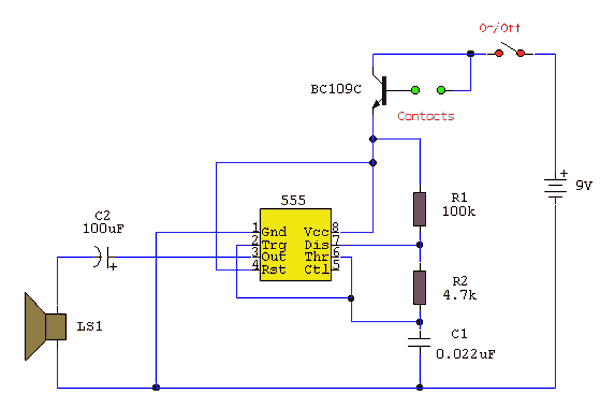
yeah, i think im gonna build the little one I posted, seems easier, yet I dont know what type of buzzer/speaker to use. I bought a 12V piezo siren from radioshack, but its loud even with a 9volt - I just hope those resistors wont limit the siren. The second observation I noticed it the transistors...it looks like there is 2 of them, or am I mistaken, I dont quite understand. but from the actual circuit (which I found online), I only see 1.

Here is the completed circuit, but im not gonna make the fancy PCB, ill just use wires for the probes, and a radioshack board.

**broken link removed**
 
Last edited:
I bought a 12V piezo siren from radioshack, but its loud even with a 9volt
Good.

I just hope those resistors wont limit the siren.
If the resistance of the water is less than ~1.6 MΩ the thing should work.

there is 2 of them, or am I mistaken, I dont quite understand. but from the actual circuit (which I found online), I only see 1.
It's a Darlington pair, integrated onto one chip.
Physically, it looks like one transistor.
Electrically, it acts like one very high β transistor.
 
Last edited:
ok, I tested the water, and it will work. im gonna order than transistor, and build this thing. Antoher quick question, which is probably a basic question is: why are the resistors marked in ohms. if they resist volts, shouldn't it tell you how many volts it limits through it? In other words, is there a formula or something that will tell me for example: I have a 9volt battery, if I put this 10k ohm resistor in line with it, how many volts will be on the other end.

thanks for the info
 
Last edited:
why are the resistors marked in ohms. if they resist volts

Georg Simon Ohm told us that they resist the flow of current; they don't resist the voltage across them.
Resistors could be marked as voltage/current just as 1 mA meter movements [1 mA = a full scale reading] used in VOMs are marked as 1000 Ω/volt, but there are an infinite number of volts/amp combinations that could represent one ohm, and the VOM meter movements might take 0.4 v across them for a full-scale reading.

E = IR so 9 v/10 kΩ = 0.9 mA of current.

9v/1.6 MΩ = 5.6 µA.

In analyzing your circuit I would first assume that when the transistor is fully "on", looking into the base lead you see 1 v across each PN junction, which gives 2 v.
2 v across 470 kΩ gives 4.3 µA.
Assuming the base current is >10x less than this value the current through the 10 kΩ resistor and the water is also 4.3 µA.

(9-2)/ (4.3 µA) = 1.6 MΩ.

For this circuit more precision isn't necessary; if it was I'd also need to know the V I curve for your audible indicator, BUZ, and the current gain, β, at the currents of interest, of your Darlington pair, .

If this circuit will see temperature extremes or voltages down to 7 v or you would want to make many of these, you may need to know the range of these values more precisely, or replace the 470 kΩ resistor with a pot.
 
Well, im not sure, but I just built that water alarm from teh schematic I posted above. Its really simple, just 2 resistors, and a darlington transistor. Mine works prefectly, even wiht the 12 volt piezo siren running on 9 volts. I gave this to my grandparents to stop their basement from flooding again.
 
I made the one given on the first post and its working fine for me, contacts are 5mm apart.

What surface area does each contact present to the other? My resistance calculation was for one sq. cm plates one mm apart.

There is an order of magitude resistance range for the water and possibly as much in the circuitry triggering point.
 
Distilled water does not conduct.
Acid or alkaline water is a dead short.
What are you measuring?
 
I was wondering if anyone can give me a factor with which id have to scale up the resistances (and any other components), for a circuit that is detecting the presence of water that is semi distilled (20-200k/cm or 5-50 micro siemens/cm) with the 2 sensing contacts at a max of 50 mm:confused: Seem to be no commercial options available

also is the capacitor neccessary?

Thanks

water_activated_alarm.gif
 
Distilled water has such a high resistance that it is used for cooling high voltage circuits.
It would be difficult to make a circuit detect distilled water.
 
(20-200k/cm or 5-50 micro siemens/cm) with the 2 sensing contacts at a max of 50 mm

So 5 micromhos = 200 KΩ-cm = ρ (i.e., rho)
50 mm (=5 cm) apart,
each probe presents 1 sq. mm (0.01 sq. cm) surface area to the other?

Neglecting edge effects,
R = ρ*L/A = [200 KΩ*5/0.01] = 100 MΩ resistance

You might need a special opamp circuit.
:eek:

If you put the sensor in series with 100 VDC you'll have an almost ideal 1 to 10 uA current source.
If you can find a transistor that has its gain spec'ed down to ~1 uA you feed the current into the base of this transistor and adjust the collector resistor to suit.
If not, find an opamp that has an Ib << 1 uA. Not too hard nowadays.

Also, almost any thing has an input capacitance of >5 pF. 100 MΩ with 5 pF gives a 10-90% response time of ~ 1 mS, which is plenty fast. For a 1 second response time you could go 5000 pF input capacitance.
 
Last edited:
If you put the sensor in series with 100 VDC you'll have an almost ideal 1 to 10 uA current source.
If you can find a transistor that has its gain spec'ed down to ~1 uA you feed the current into the base of this transistor and adjust the collector resistor to suit.
If not, find an opamp that has an Ib << 1 uA. Not too hard nowadays.

Also, almost any thing has an input capacitance of >5 pF. 100 MΩ with 5 pF gives a 10-90% response time of ~ 1 mS, which is plenty fast. For a 1 second response time you could go 5000 pF input capacitance.

Is is as simple as what you said above, or will i still need the 555 chip thing :eek: lol sorry for being a bit dim
 
Is is as simple as what you said above, or will i still need the 555 chip thing :eek: lol sorry for being a bit dim

It might still turn out to be not too simple.

Regarding the 555, what kind of indication do you want when water is detected?
Are there any other constraints on this "transducer" besides response time? Motors nearby putting electrical noise everywhere?
Battery-operated-only design?
 
It might still turn out to be not too simple.

Regarding the 555, what kind of indication do you want when water is detected?
Are there any other constraints on this "transducer" besides response time? Motors nearby putting electrical noise everywhere?
Battery-operated-only design?


not really. response time, and a simple visual or audio output, like an LED/buzzer. the placement is pretty high so cant imagine there will be any electrical noise
 
not really. response time, and a simple visual or audio output, like an LED/buzzer. the placement is pretty high so cant imagine there will be any electrical noise

Is one level sensing probe necessarily grounded or can both be isolated from ground?
 
**broken link removed**

The 24 VAC xformer is a doorbell type.
The WT is a wall transformer or "adaptor" that puts out +12 v at any current.
C1 should be rated at 20 V and be a few uF, mounted close to the opamp.
All parts are available from www.hosfelt.com.
Do not short WATER terminals together.

Yu wan' me 'splain how sirkut supposdowuk???
 
Last edited:
A lousy old LM324 has a max input current of 0.25uA. Your 20M feedback resistor has such a high resistance that the output will try to be -5V without an input. Use a Fet-input opamp.

You have an extremely high negative input at the sensor probe that will damage the opamp if the probes short together.
 
Status
Not open for further replies.

Latest threads

New Articles From Microcontroller Tips

Back
Top